| Test | Push-Pull_LM4562_NoBias_22ohm | Push-Pull_LM4562_NoBias_10ohm |
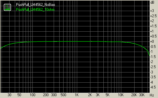
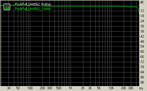
| Frequency response (from 40 Hz to 15 kHz), dB: | +0.02, -0.14 | +0.02, -0.14 |
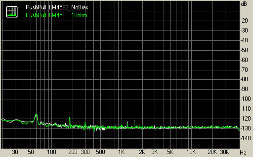
| Noise level, dB (A): | -96.1 | -96.2 |
| Dynamic range, dB (A): | 95.7 | 95.6 |
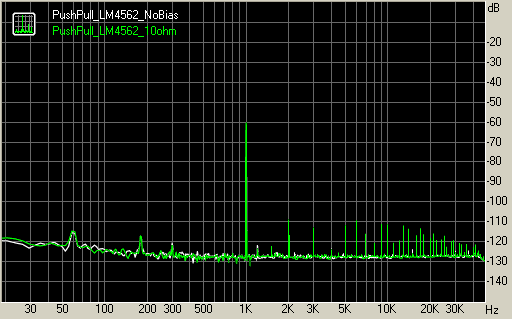
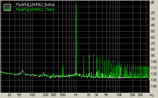
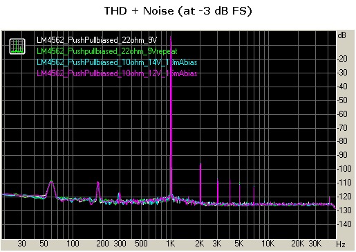
| THD, %: | 0.0065 | 0.0081 |
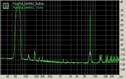
| IMD + Noise, %: | 0.0061 | 0.0078 |
| Stereo crosstalk, dB: | -50.2 | -50.7 |
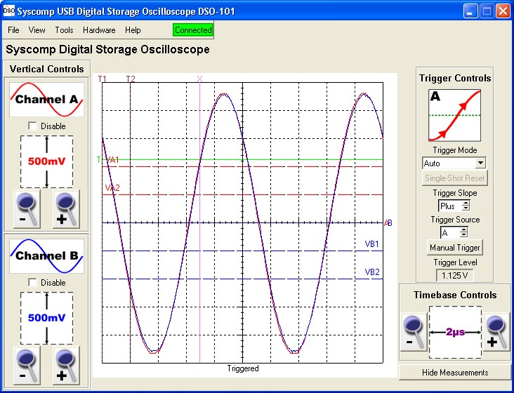
100 kHz Response with RL=10 ohm showing input and output