
A-Weight Filter Set
Aug 15, 2013 / Oct 24, 2020
This note presents measured total rms noise voltage results for a basic A-Weighting audio filter based on an Ampex circuit as described here,
and in combination with a 20 kHz 5th order LP Butterworth filter as described here.
Although there has been much discussion of the usefulness of A-Weight filtered specifications, it is the most commonly used measurement filtering found in
commercial specifications of audio electronics for noise and S/N. It is therefore useful for verifying published specifications.
With reasonable care in choice of resistors and capacitors, the total noise (and S/N ratio) for audio circuits can be measured to an accuracy of ~ 1dB which will be sufficient
for many purposes. The circuit is not intended for precision comparisons.
In some cases, since exact capacitor values were not handy, individual components were measured and selected and parallel combinations were substituted to achieve values close to those recommended.
The circuits were assembled on a breadboard and mounted in a shielded box. Both NE5534AP and OPA134PA op-amps were tested.
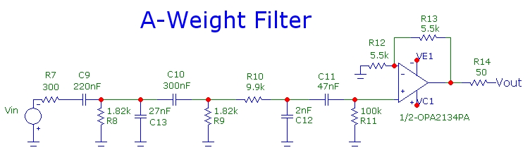
A-Weight Circuit
The first circuit is the A-Weight filter using two OPA134A opamps (the combined circuit below uses dual OPA2134 opamps):

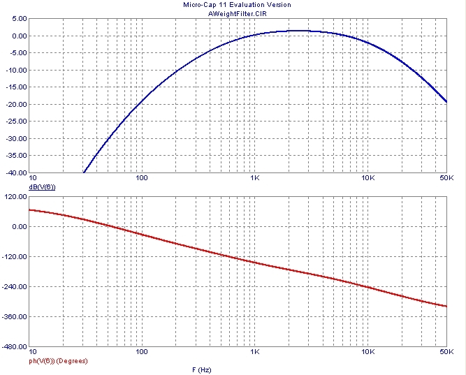
The spectral response using Right Mark Audio Analyzer and a Creative X-Fi Elite Pro sound card with sampling at 24 bit/96kHz (providing a flat response to over 40 kHz and an equivalent
noise bandwidth of 46kHz) is shown below.
Results are very close to the standard A-Weight curve up to ~ 5 kHz but probably due to the simplicity of the circuit, the
response does not fall off fast enough at higher frequencies compared to the standard A-Weight response profile. (For a flat noise spectrum, the total RMS noise voltage measured using this
A-Weight circuit will measure about 5% too high (or 0.4dB too high).
Nevertheless, the circuit is sufficient for most practical purposes and for approximate comparison
with published audio gear specifications to within ~ 1dB. (The dB scale is offset due to the RMAA measurement conditions). The actual circuit gain at 1 kHz was measured to be 0.0 +/- 0.1dB).
Spectral response measurements were performed at a nominal signal level of 250mVpeak at 1 kHz:

The NE5534 and OPA134 op-amps have similar performance (as expected since the op-amps merely provide input and output buffering/isolation). The circuit
contributes a noise level in a 20 kHz noise BW of about 5 uVrms with the input open and 4 uVrms with the input shorted. This noise is mainly due to thermal
noise contributed by the 100kohm resistor at the non-inverting input of the output stage op-amp. This circuit is most useful when used with a low-noise
preamplifier stage between the device to be measured and the output rms voltage measuring device.
The NE5534 version has an output offset DC voltage of ~ 50mV (due to the NE5534 high bias current of 500 nA combined with the 100kohm resistor)
while the FET input OPA134 has a very low output offset voltage of < 0.2mV. For most practical applications this will not be important unless this
circuit is DC coupled to an additional signal processing stage, such as a bandwidth filtering section.
Combined A-Weight and 20 kHz LP Filter
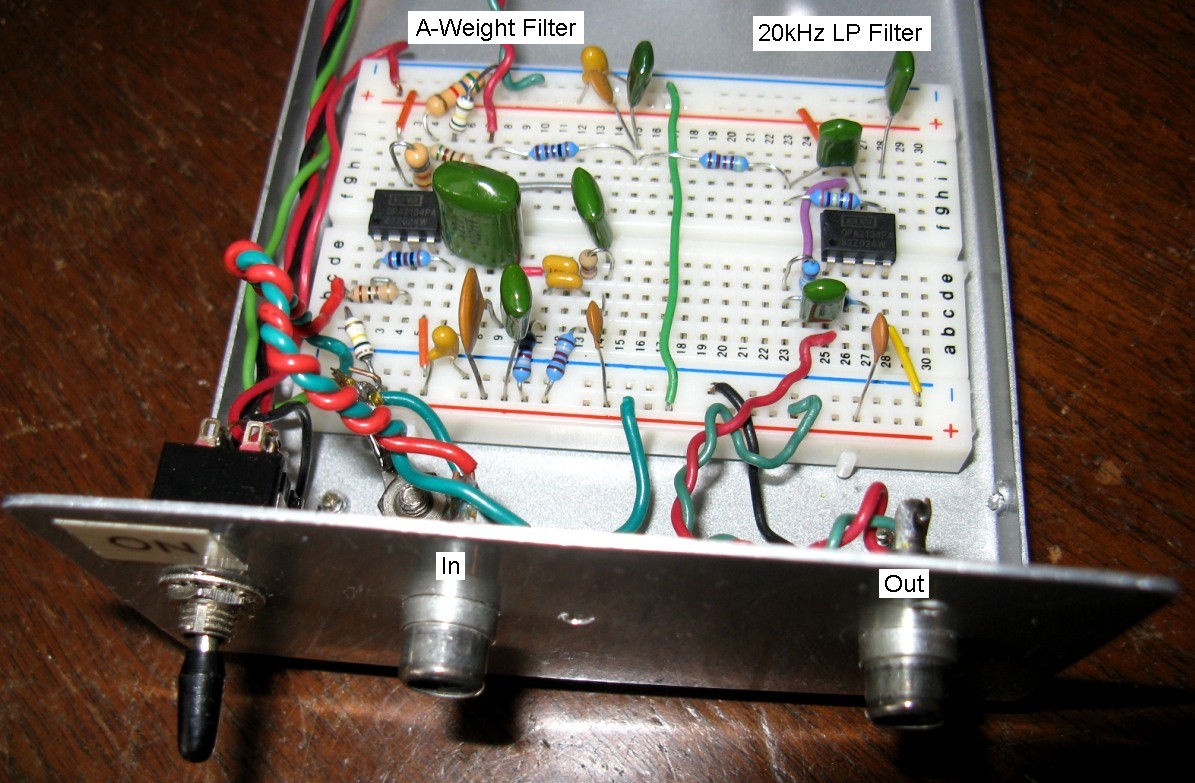
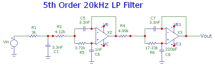
Using the circuits mentioned above, the combined A-Weight filter and a 5th order 20 kHz LP filter was assembled as shown using dual OPA2134PA opamps. A switch
was added allowing for easy comparison of unfiltered noise in 20 kHz and A-Weighted noise in 20 kHz. In some audio devices tested, the difference in total noise
measurements is ~ 2 dB, in good agreement the difference expected for a spectrally flat noise source:
The schematic diagram and basic simulation results are shown below for the A-Weight circuit and 5th order 20kHz filter built here.

The responses of the combined circuit, the 20 kHz LP filter alone and the measurement system (including a wide-band low noise post amplifier), as measured using RMAA at a nominal signal level of 300 mVp at 1 kHz is shown below.
The actual gain at 1 kHz of the combined A-Weight filter and 20 kHz filter was measured carefully to be 0.0 +/- 0.1dB. A simple RC high-pass filter with a break frequency of 16 Hz
is used at the input of the first buffer op-amp stage to filter out noise contributions at very low sub-audio frequencies:

The total output noise of this combination circuit was measured to be 12uVrms using a very low noise high-gain preamplifier.
This combined filtering circuit is not a particularly low-noise design.
Therefore, in order to perform useful noise measurements on target circuits with low noise, the device to be tested DUT should be first amplified with a
very low noise wide-band calibrated gain block before passing to the A-Weight+20kHz filter combination.
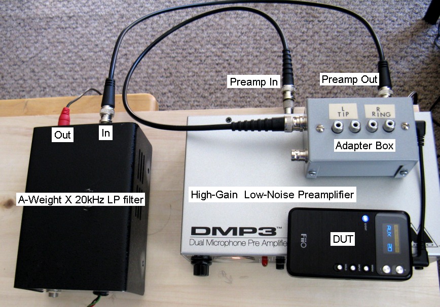
The layout I use shown below incorporates an M-Audio DMP3 low-noise audio preamplifier. It is not difficult to build a fairly simple very low noise
low distortion 60 dB audio gain block curcuit with a noise bandwidth of 45kHz using high-performance opamps such as the LM4562NA.
Using this configuration, total noise voltages, A-Weighted and within a noise BW of 20 kHz, for a DUT can be measured down to ~ 0.5 uVrms
without the noise contribution of the combined post-filter affecting the measurements.
As mentioned above, the A-Weight circuit described above will measure about 0.4dB (or x1.05) too high (for uniform noise). The total measured noise can be corrected by this amount.
The rms total noise measurement was obtained from a custom application Wavemon which samples the calibrated line-in of the X-Fi Elite Pro sound card at 24bit/96kHz and
computes the rms noise level:

Some measured results on audio electronics are:
FiiO (E17) headphone amplifier  0dB Gain Range  Max Volume   Line-In open:
    5.0 uVrms (20kHz LPF)    3.8 uVrms (A-W + 20kHz LPF)

Samsung Galaxy S4 headphone output: Max volume .. silent track playback:
    3.3 uVrms (20kHz LPF)    2.5 uVrms (A-W + 20kHz LPF)
The differences in rms total noise with [A-Weight + 20kHz LP Filtering] and unweighted 20kHz LP filtering alone are about 2.3 dB consistent with the noise spectrum in the 20 kHz
measurement bandwidth being close to "white" as discussed below.
A-Weight Correction Factor for a Flat Noise Spectrum
How much does A-Weighing affect the S/N ratio for noise measurements? Obviously this will depend on the frequency dependence of the spectral noise density.
However as a very crude benchmark, if we assume an idealistic UNIFORM noise spectral density from DC to 40kHz, it is easy to integrate the complex
A-Weight analytical transfer function
and obtain an "A-Weight correction factor" for the corresponding measurement noise-bandwidth. In this idealistic case, the A-Weighted rms noise will always be lower
than the unweighted value. Assuming a measurement noise-bandwidth (NBW) with infinitely sharp (brick wall) rolloff, the noise-reduction factors are:
    NBW            A-Weight factor
   20 kHz            -2.05 dB
   30 kHz            -3.59 dB
   40 kHz            -4.78 dB
In many real cases however, the differences between unweighted and A-Weighed measurements for a standard 20 kHz BW will be significantly larger than the ideal factors above due to nonuniform and
higher noise densities at higher frequencies and also 1/F increasing noise at low frequencies compared to noise density at the nominal 0dB frequency of 1 kHz.
This means that the S/N ratio with A-Weighing can be much higher than unweighed.