
Digilent Analog Discovery Characteristics
Feb 20, 2013
This article presents some basic characteristics of the Digilent Analog Discovery design kit.
Connections were made using the Digilent Discovery BNC adapter unit.
Oscilloscope Frequency Response :
A calibrated 10MHz Syscomp Design function generator was used to determine the frequency response of the Discovery scope inputs.
The response measurements were performed with a 47ohm input termination of the function generator with very short connections to the Discovery scope with a total shunt capacitance of ~ 50pF
including the Discovery input capacitance, ensuring the input pole RC rolloff didn't effect the response measurements.
The Discovery scope response was flat to 1 MHz. At 5 MHz the response is down by ~ 1% (-0.9dB) and 10MHz the response is down by ~ 2.5% (-0.22dB).
Oscilloscope Noise Floor:
The background noise floor was 800uV - 1mV RMS with open or shorted input termination as shown below:

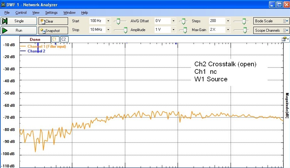
Oscilloscope Crosstalk:
Crosstalk between the two oscilloscope channels were performed with the Discovery function generator W1 scanned from 100 kHz to 10MHz at a 1Vpeak level using the Waveforms Bode plot software. The first two response plots show
the oscilloscope Ch2 input crosstalk with either open or 50 Ω input termination with W1 connected to Ch1. The 2' coax cable with a Cf of 60pF was used for the connection.
The third response plot shows the crosstalk in Ch2 from the W1 generator with no connection from W1 to Ch1:


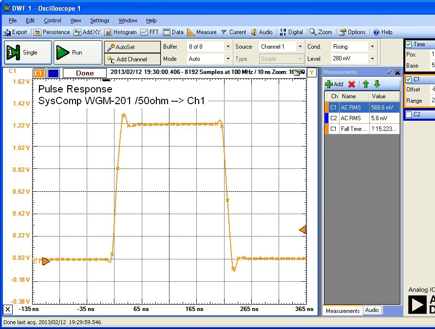
Pulse Response:
Plots below show the pulse characteristics with a pulse amplitude of 1.2V. A 2' cable was used from the Discovery W1 output to Ch1 with W1 either direct or with the 50 Ω source termination provided on the Discovery BNC adapter.
In the first plot, the structure on the leading and trailing edge of the pulse is partly due to the strong reflection at ~ 10ns delay in the 2' coax. This is because the Discovery W1 output, without source termination, presents a
very low impedance (~ 0.2 ohm) which causes a reflection of ~ 100% at the 1MΩ scope input impedance as well as an inverted 100% reflection at the W1 end.
The third plot shows the Discovery scope response using a 10MHz Syscomp Design function generator with a 50 Ω input termination showing very
good transient response capability of the oscilloscope input channels, consistent with an effective measurement bandwidth of 10MHz or greater. This is not surprising as the Discovery uses a sample rate
of 100 MSPS.


The impulse response from a 2 ns wide electrical pulse with amplitude ~ 8Vpeak from an avalanche transistor circuit is shown below:
