Photodiode Speed and Reverse Bias
Nov 05, 2015
Semiconductor photodiodes are used for a wide variety of purposes from high-speed telecommunications systems to lower speed industrial control applications.
Typically, larger area photodiodes are used in low-speed applications and are often used at zero bias. It is well known that the speed of a photodiode is determined
by intrinsic processes involving the light wavelength and semiconductor material comprising the junction photodiode as well as the reverse-bias voltage applied to
the junction. Furthermore, a reverse-bias voltage applied to a junction photodiode lowers the capacitance which will interact with the amplifier circuit to determine
the overall circuit speed as well as total noise of the combined photodiode-amplifier circuit.
This article demonstrates how the speed of a typical mid-frequency Si photodiode depends on the reverse-bias voltage applied to the photodiode.
The Transimpedance Circuit
A Vishay BPW24R Si photodiode with a tr/tf of 7ns (BW ~ 50MHz @ -20V bias) was used in the transimpedance amplifier circuit below:
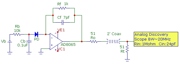
The AD8065 has a GBW product of 65MHz and a total equivalent input capacitance in this circuit of 6.6pF with a slew-rate of ~ 180V/µs, sufficiently fast
for the signal levels in the measurement. For the circuit shown with Rf=1kΩ and
Cf = 7.5pF (including stray) chosen to provide approximately the maximally flat transimpedance response, the circuit Tz bandwidth (for an ideal current source) is about 21MHz.
The Digilent Analog Discovery scope used
for the measurements has a -3db bandwidth comparable to this. Therefore the measurement BW limitation for the Tz circuit and scope combined is somewhat
less than 20MHz.
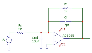
To verify the Tz circuit bandwidth WITHOUT using a photodiode and LED optical source as a current source, the circuit below, using a voltage source Vs can be used with the corresponding
Thevenized equivalent current source shown below (the output section with Ro, Rt is not shown for simplicity) . A simulation shows that although this test circuit is somewhat different than the original Tz circuit with
an equivalent shunt resistance Rs of 5kΩ from inverting input to ground, the resultant Tz circuit response is almost identical with 20.5MHz BW and with
almost identical Q value. A shunt capacitance of 10pF was added to represent the worst-case photodiode capacitance (at zero bias). The total capacitance from the
INV input to ground is therefore about 18pF (including op-amp and stray).
The Tz bandwidth doesn't change significantly as the shunt capacitance changes from 10 to 3 pF (corresponding to the range of PD capacitance change with the reverse bias range studied here):

The frequency response of this test-circuit is shown below, with Vs set at 1Vpeak, corresponding to an equivalent midband photocurrent of 200µA or an output
voltage of 200mVpeak.
The equivalent circuit, with the original voltage source, is essentially an inverting amplifier with a midband gain of 0.1 or -20dB (note that Ro and Rt at the output
comprise a -6dB divider). The response is nearly flat to 10MHz with
a very slight rise corresponding to a value of Q ~ 0.75 and consistent with f-3db ~ 20MHz:

Photodiode Response Versus Reverse Bias
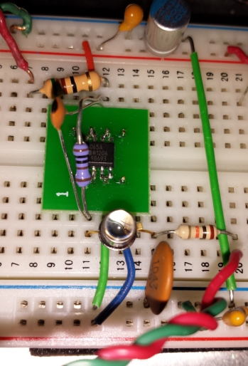
The original circuit with photodiode and a variable reverse bias voltage was tested for response speed using a
pulsed 870nm high-speed infrared LED with a falltime of ~ 12ns
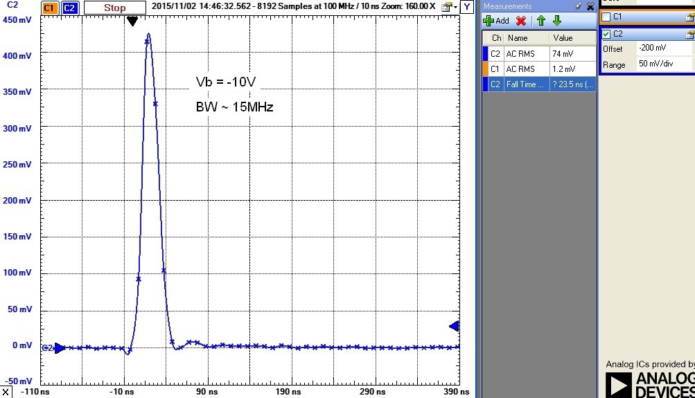
corresponding to an impulse BW of ~ 30MHz. The setup is shown below and results for reverse bias ranging from zero to -15V bias are shown. The Tz circuit
BW, as determined by simulation, does not change significantly as the photodiode capacitance is lowered with higher reverse bias, so the falltime changes measured below are due solely to
intrinsic processes within the photodiode having to do with depletion region changes with bias in the PN junction and related internal photocarrier dynamics. A simple estimate
of the photodiode intrinsic BW from the time response is provided with
BW ~ 0.35/tr
where tr is the measured 90-10% falltime as shown. The traces show the 10ns sample points (100MHz sample rate)
. The photodiode BW dependence on reverse bias will also depend on the optical wavelength and at Vb=0 the response time will change significantly at higher
incident power levels due to the photodiode being slightly forward biased leading to a nonlinear response: