Calculates the exact voltage gain Av=V0/Vs, the corresponding dB values and complex input impedances for 3 frequencies f1, f2 and f3
using general expressions derived from feedback circuit analysis.
The op-amp is assumed ideal except for a finite gain-bandwidth product. A single-pole open-loop gain profile is assumed for the op-amp.
Also finds the high-pass and low-pass -3db frequencies relative to the "mid-band" value computed at f2.
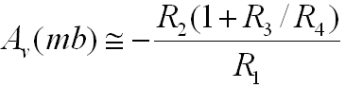
The above circuit is a fairly general inverting amplifier configuration with a t-network in the feedback loop.
This type of t-network enables high gains to be achieved in the inverting amplifier configuration without the use of high feedback
resistance values. Since the midband gain of the single-feedback-resistance inverting amplifier configuration is -Rf/Ri and Ri involves the source inpedance,
high values of source impedance would require very high Rf values in the single feedback impedance case, compared to the
t-network configuration. For the t-network configuration, for an ideal op-amp with infinite GBW, the midband gain
(assuming all shunt capacitative impedances are very high, and Rs << R0||R1) is:
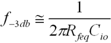
where Rfeq is the equivalent feedback resistance for the t-network.
The feedback t-network gain has an extra factor of R2*R3/R4 increasing the effective total feedback resistance above R2+R3.
High values of this term are achieved with low values of R4 relative to R2*R3. If R3 << R2 and for high gain:
Assuming the high-frequency rolloff is determined by the feedback network (and not limited by the GBW of the op-amp),
if C2 and C3 are small enough, the -3db high frequency is determined by the pole formed by Rfeq and Cio:
However, it must be noted that feedback analysis of this circuit with a feedback t-network shows that the noise gain, which determines
the actual circuit bandwidth, when combined with op-amp GBW product, is increased considerably from what one might naively expect based
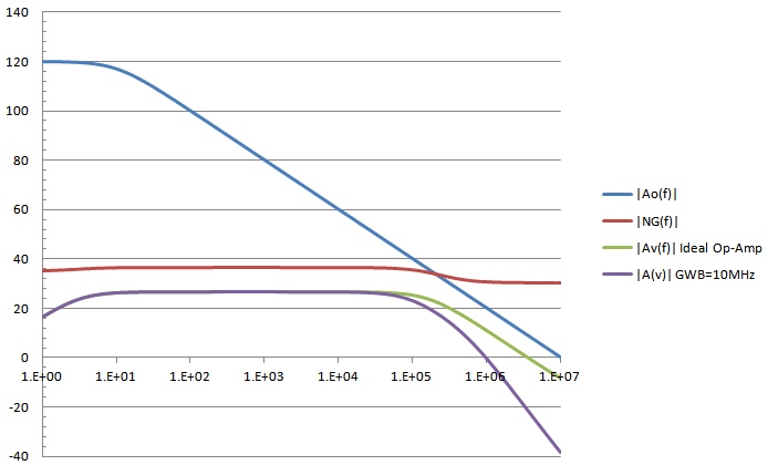
on the corresponding single feedback resistor circuit case. For example, using the default parameters above, the Rfeq = 1.032 Mohm and the circuit gain is Av ~ -22.
Naively, one might expect the mid-band noise gain to be 22+1 = 23 as for the single feedback resistor circuit with the same Rf value. However, the t-network
causes the noise gain to be increased by an additional amount (1 + R3/R4) = 46.5 so the total enhanced noise-gain for this specific t-network example
is in fact 69.5, more than 3 times higher than the single feedback resistor noise-gain! This means that even without any external component
capacitative rolloff effects, the circuit bandwidth using an op-amp with GBW=10MHz will be only 10MHz/69.5 ~ 144kHz. By contrast, the pole frequency as
determined by Rfeq and Cio (0.5pf) in this case is 308kHz. The net result would be a circuit with gain rolloff mainly limited by the op-amp GBW
to a value of about 108kHz. The actual f3db circuit bandwidth above is 88kHz however because of the rolloff caused by the pole with C2 (20pF) and R2.
The response curves below show the open-loop gain profile for a 10MHz op-amp with single-pole rolloff, noise gain, and amplifier response for the circuit shown above.
Responses for both an ideal (infinite GBW op-amp) and the 10MHz GBW op-amp are shown. Note that the mid-band noise gain
is about 10db higher than the signal gain, a consequence of the t-network. By comparison, a simple inverting op-amp circuit with a single feedback resistor
of the same value as the equivalent for the t-network (1.032 Mohm) would have a noise gain of 27.2db, almost identical to the signal gain of 26.8db with a considerably higher f3db circuit BW of 200kHz: