WGM-201 Advanced Waveform Generator Usage
June 13, 2012
The Syscomp Electronic Design Ltd. WGM-201 Advanced Waveform Generator provides sine wave output up to 10 MHz as well as arbitrary programmable waveform shapes up to 3 MHz.
The WGM-201 is specified as having an output resistance of 150 ohm. A typical usage of the sine output of this generator would be to measure frequency response of circuits
up to the 10 MHz limit.
For reasonably accurate measurements requiring calibration, it is useful to measure the precise output-level of the generator up to 10 MHz.
It is important to understand
that above ~ 1 MHz, small circuit capacitance values can shunt the output of the generator simply from the complex voltage divider network formed by the 150 ohm internal
impedance and the capacitative reactance. In order to minimize the relative effects of shunt capacitance at higher frequencies, the generator output can be terminated
with lower values of resistance. For example, with a 50 ohm termination at the generator output, the effective (Thevenin) resistance of the generator is the parallel combination
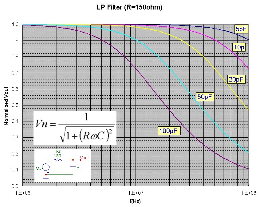
of 150 and 50 ohm or 37.5 ohm. Of course the effective Thevenin output voltage is also lowered (by 1/4) from the nominal value. To demonstrate the importance of shunt
capacitance, the following 2 graphs show the effect of load capacitance on the normalized voltage output (assuming a load with much higher resistance than the 150 ohm generator resistance).
The first set of plots show the dramatic filtering effect above 1 MHz as shunt capacitance is varied, a simple result of the complex voltage divider in this single-pole network.
The second set of plots, with a termination resistance of 50ohm (or Rth=37.5ohm) demonstrates the cutoff moving to higher frequencies:

WGM-201 Waveform Generator Output Calibration
Since I don't have a wide-bandwidth oscilloscope, I designed a circuit involving a peak-detector using a 1N34a Ge diode and a very high slew-rate and high bandwidth op-amp
to measure the peak sine wave amplitude of the WGM-201. Details of the circuit are presented below. The WGM-201 was terminated with 50 ohm. The capacitance load of the measuring circuit was ~ 25 pF which will cause
completely negligible shunting (see curves above). The peak-detector circuit was calibrated and corrected to allow for the very slight diode drop across the Ge diode which is independent
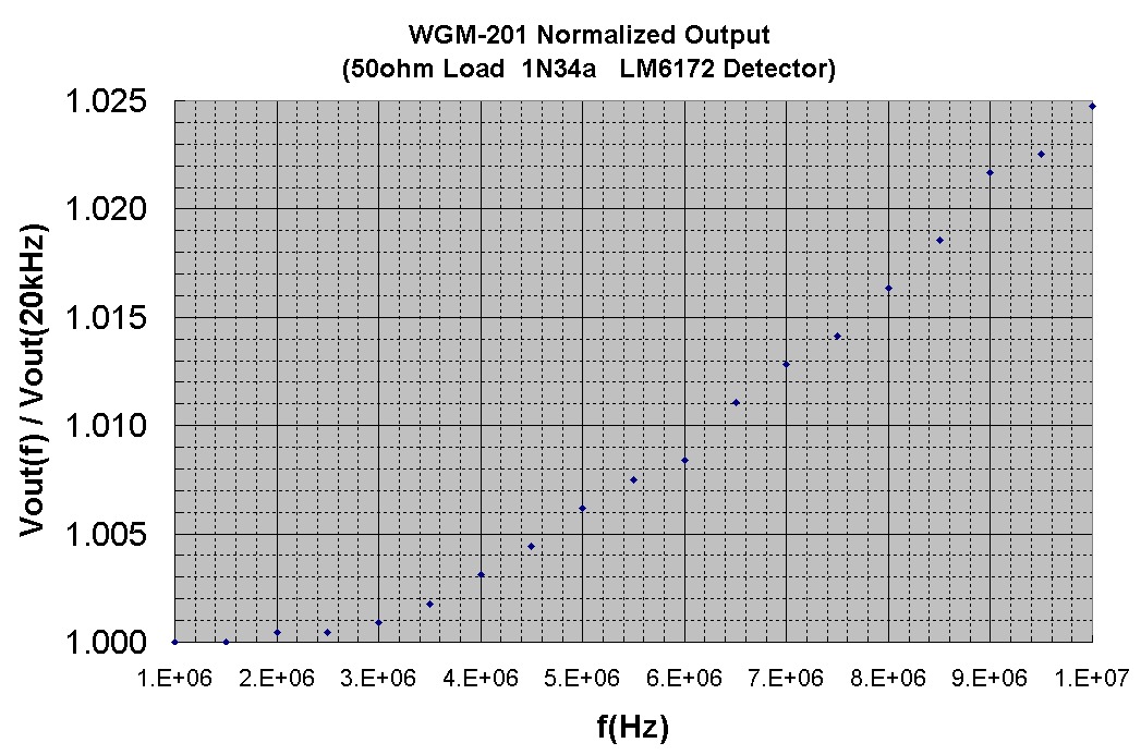
of frequency at least up to 10 MHz. The normalized response of the WGM-201 generator, for a nominal signal level of ~ 0.5Vpeak is shown below. These results agree with those
measured directly using a high-speed oscilloscope (private communication Syscomp Design). The WGM-201 output level is flat up to about 2 MHz and gradually increases by
about 2.5% up to 10 MHz:
DSO-101 Digital Oscilloscope Response Calibration
Using the calibration results above for the 10 MHz WGM-201 sine generator, the peak-amplitude frequency response of the Syscomp Electronic Design Ltd.
DSO-101 2 MHz USB digital storage oscilloscope was measured.
Although this digital USB oscilloscope is really designed for measurement at frequencies up to 2 MHz, the sampling system can still sample frequencies up to 10 MHz although the
display waveform is rather "jagged".
Still, it is interesting to measure the response curve. Using the identical measurement configuration as used above for WGM-201 calibration, and correcting for the 2.5% increase in level above 1 MHz of the WGM-201 generator output,
the normalized peak amplitude display, for a nominal signal level of ~ 1Vpeak, is shown below:

Measurement Configuration
The half-wave rectifier circuit used to measure peak AC voltage levels up to 10 MHz is shown below:

The LM6172 is a high-speed 100 MHz GBW op-amp with unity-gain stability and a very high slew-rate of 3000 V/μs configured as a high-speed follower. This op-amp can easily drive the half-wave rectifier circuit at its output.
Since this op-amp has a fairly high input bias current of 1.5uA, a 1 kohm +input termination resistor was used to ensure negligible output voltage offset driving the half-wave rectifier output.
The input high-pass filter removes any DC and
has a cutoff of ~ 700 Hz and therefore is intended to be used above ~ 10kHz. This op-amp circuit can therefore can be used as a standard 1kohm load with small capacitance load to
measure other op-amp circuit outputs. The LM6172 output drives a 1N34a half-wave peak detector circuit with a 20 Mohm load and 0.01 uF filter capacitor. The 20 Mohm resistance consists of
a 10 Mohm resistor and a standard 10 Mohm input DVM measuring DC voltage. The accuracy of the DVM ranges was checked using a 0.1% precision DC voltage reference IC.
For a fixed input voltage level, the rectified output DC voltage level is constant from 10 kHz to at least 10 MHz with negligible
ripple. This was confirmed with a circuit simulator using the complete diode characteristic.
Amplitude calibration from input to output was performed at a lower frequency and compensates for the diode voltage drop in the rectifier circuit. The detector circuit and the entire
measuring configuration used for all the measurements above are shown below:


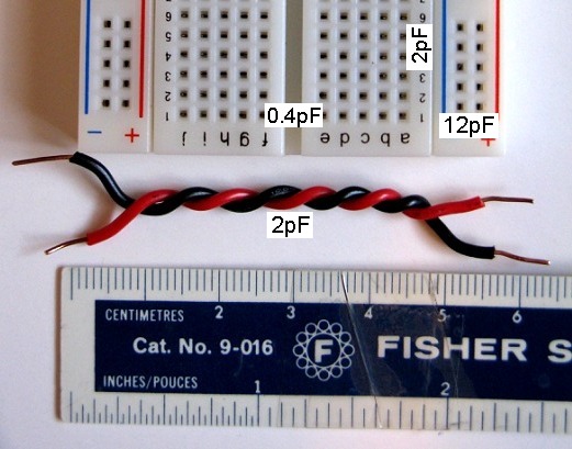
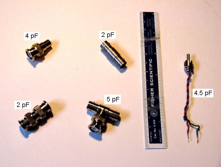
Some Useful Capacitance Values
The capacitance values of some BNC connectors are shown below. Standard RG58a/U 50ohm test cable has a capacitance of 30 pF/foot.
Typical measured stray capacitance values for various connections on a 3"x2" protoboard are shown below. Note that the capacitance across the center channel is quite low (0.4pF) while
the capacitance between adjacent tracks, corresponding to adjacent pins of DIP pinouts, is much higher at 2pF. This has obvious implications in feedback stray capacitance (from inverting input to output) for single versus dual op-amp
DIP configurations when measured on these types of breadboards: