
Op-amp Output Capacitance Isolation
This note demonstrates and discusses the common practice of isolation of an op-amp output from load capacitance
by using an external output series resistance outside the feedback loop. Other approaches for isolation are discussed in
the references.
The stability of any op-amp circuit depends only on the value of the "loop gain" Ao(s)*B(s)
where Ao(s) is the op-amp open-loop frequency-dependent gain function and B(s) (or beta) is the frequency dependent feedback fraction.
Instability will result if, at the frequency where "|Ao(s)*B(s)| = 1, the phase angle of Ao(s)B(s) approaches -180 deg leading to oscillation. Note that both the
built-in phase angle inherent in the op-amp as well as the phase angle of added feedback components (B) both effect the stability condition.
Typically good stability design requires the "phase margin" (180 + pha(AB)) to be 60 deg. or larger.
To simplify the discussion, a generic op-amp is modeled in a basic non-inverting amplifier configuration as ideal except for two characteristics:
- a finite gain-bandwidth product GBW = 50 MHz, modeled as a single-pole open-loop gain function
- a finite output open-loop resistance, Ro = 15 ohm.
The schematic used to model the circuit discussed here is shown below. Fixed feedback resistances of 6.8 kohm are used
The internal op-amp output resistance Ro = 15 ohm is not shown. A fixed load resistance of 2 kohm is used. The results shown below relate to
changes in response as the load capacitance Cl and output series resistor Rs are added:
The total output load impedance ZL includes the isolation series resistance Rs in series with the paralleled load capacitance Cl and resistor Rl:
   ZL = Rs + Zout
   Zout = Rl||Z(Cl)  = Rl/(s*Cl)/[Rl + 1/(s*Cl)]
   s = jw = j*2*pi*f
With zero op-amp output resistance, Ro = 0, the amplifier transfer function and output gain are: Vo(s) = 1/B * Ao(s)*B/(1 + Ao(s)*B)
Av(s) = Vo(s) * Zout/Zload
where B is the feedback fraction Zi/(Zf + Zi) and Ao(s) is the op-amp unloaded single-pole open-loop gain function (the noise-gain is 1/B): Ao(s)= Aoo/(1 + jf/fpo)
To simplify the discussion and focus on output capacitance loading effects, the feedback network impedances Zi, Zf will be taken as real (resistive)
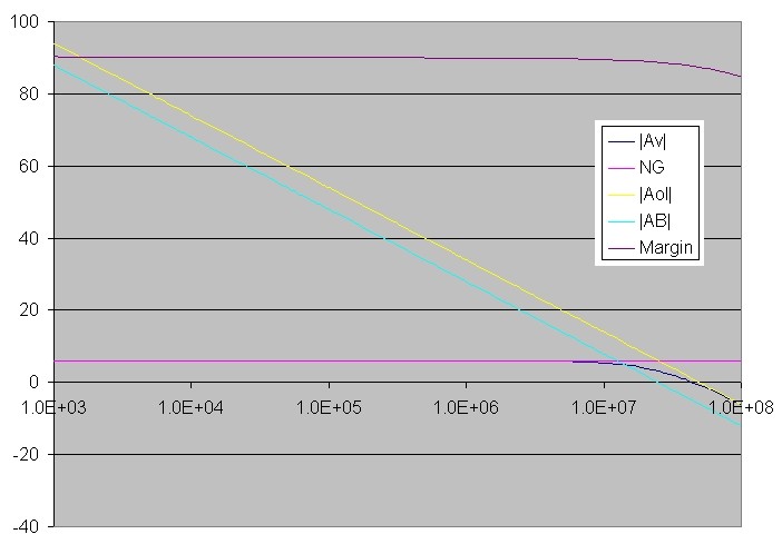
so that B is frequency independent. The amplifier gain, noise gain, open-loop gain, loop-gain and phase angle are shown below for this ideal case
with Ro = 0, Rs = 0, Rl = 2kohm and Cl = 10 pF (negligible capacitance load). The noise-gain is 2 (6 dB) in this non-inverting configuration and is
equal to the circuit voltage gain. The 3dB bandwidth is 50 MHz/NG = 25 MHz:
With a non-zero op-amp output resistance, it is easy to show that the same amplifier transfer functional form applies, but with a modified
(effective) open-loop gain function A'o(s): Vo(s) = 1/B* A'o(s)*B/(1 + A'o(s)*B)
A'o(s) = Ao(s)*(Zf + Zi)||ZL/(Ro+(Zf + Zi)||ZL)
This simply states that the op-amp effective open-loop gain function is modified to a value described by an output (complex) voltage divider.
Note that if Ro=0, A'o(s) reduces to Ao(s). Note also that since ZL is complex (due to Cl), there will be an added phase-shift to the open-loop gain
function. To simplify the discussion further, we will assume that (Zf + Zi) << ZL so that: A'o(s) = Ao(s)*ZL /(Ro + ZL)
By substituting the complex load impedance ZL into this effective open-loop gain expression, it is found that the loop gain, A'o(s)*B has an extra pole fp1 and zero fz1
along with the single pole of Ao(s): A'o(s)*B = Ao(s)* B*(Rs + Rl)/(Ro + Rs + Rl) * (1 + (Rs||Rl)*s*Cl) / (1 + ((Ro + Rs)||Rl)*s*Cl)
fp1 = 1/(2*pi*(Ro + Rs)||Rl *Cl)
fz1 = 1/(2*pi*Rs||Rl *Cl)
Note that with Rs = 0, and with Rl >> Ro (usually the case and assumed here with Rl = 2kohm), the pole frequency is 1/(2*pi*Ro*Cl) and the zero is moved to infinite frequency.
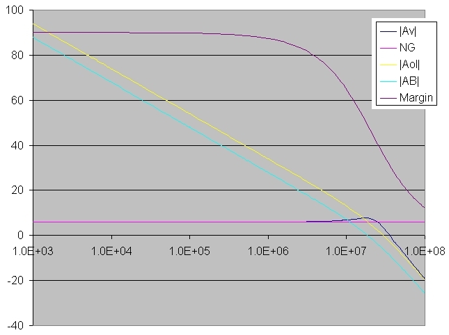
The next graph shows the modeled amplifier response including the op-amp finite output resistance Ro = 15 ohm and with significant capacitance loading
of 500 pF, but WITHOUT capacitance "isolation" with Rs = 0 . The phase margin drops to 45 deg. at the pole frequency arising from Ro and Cl at
fp1 ~ 21 MHz. The closed loop bandwidth is extended with some peaking in the response. This may not be sufficient phase margin for stability, since a real op-amp will
have extra phase accumulation (not included in the simplified single-pole model for Ao used here) for an amplifier with low gain and high-bandwidth.
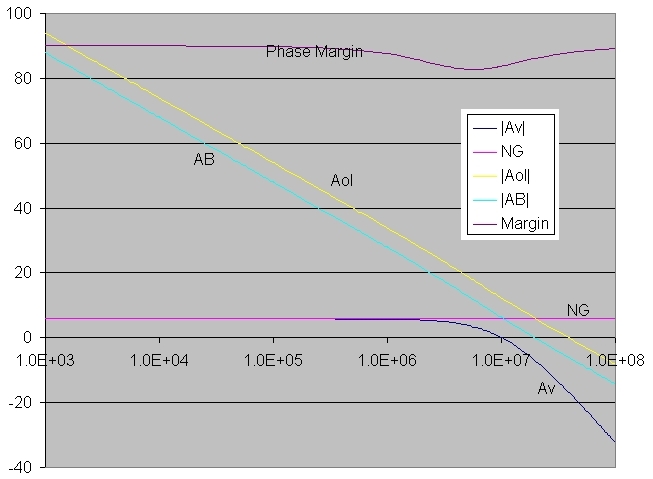
Finally, adding an output series "isolation" resistance of Rs = 50 ohm demonstrates how the added zero fz1 (due to Rs) tends to cancel out the phase shift due to the
pole at fp1. Note that although Rs lowers the pole frequency in this case to fp1 ~ 4.9 MHz, the added zero at ~ 6.4 MHz cancels the phase shift
of the pole resulting in a net phase margin of greater than 80 deg at the frequency where |A'(s)B| = 1 resulting in a stable circuit configuration, albeit with a reduced 3dB
bandwidth of 6 MHz.
References:
- "Operational Amplifiers Design and Applications", Tobey et. al. 1971 p.440
- "Op Amps Driving Capacitive Loads", Grayson King, Analog Dialog, Volume 31, Number 2, 1997
- "Feedback, Op Amps and Compensation", Intersil AN9415.3 1996