
OP AMP Test Circuit
Dec 8, 2009
Introduction:
This article presents a simple implementation of a compact convenient portable test circuit which can be used with
a low bandwidth oscilloscope to quickly check any standard voltage feedback op amp with standard pin outs. The circuit includes a 22 kHz Wien-bridge
oscillator with amplitude adjustment. The design uses a non-inverting op amp circuit configuration suitable for
basic test purposes. Component values facilitate checking offset voltage and bias current values.
The test circuit can be powered by a portable dual 6V DC battery supply. The circuit has been found useful for checking
op amps with GBW up to 500 MHz.
Circuit Descrption:
The circuit uses a classic low distortion Wien-bridge oscillator configured to run at 22 kHz.
The oscillator uses a dual LM4562 op amp with a GBW of 50 MHz and a slew rate of 20 V/us. The Radj pot is used to
adjust the oscillator output level to about 300 mV before buffering with the second amplifier in the dual.
Switch Sw1 is added to disable the Wien-bridge oscillator. This is useful during offset voltage monitoring as it eliminates
any oscillator background coupled noise on the protoboard.
The components of the oscillator can be easily changed for frequencies from hundreds of Hz to about 500 kHz.
For example, to operate at 1 kHz, substitute Rw = 1.5 kohm and Cw = 0.1 uF. At a lower frequency, the test circuit can be used
without an oscilloscope but with a typical digital multimeter which usually has AC voltage frequency response up to a few kHz.
The device under test (DUT) is configured as a standard non-inverting voltage amplifier with a signal gain of 11 with
Rf = 10 kohm and Ri = 1 kohm.
The expected peak op amp output is about 3.3V for the 300 mV input level. This is within the voltage output drive capability
of all op amps operating from a +/- 6V supply. The oscillator output level can also be increased to check op amps with R-R
capability or to verify the limits of the output level against the supply voltage.
Any standard op amp specified as being stable in a gain of 10 or less can be tested with this circuit.
Also, at 22 kHz, the required slew-rate for this output level is a low 0.5 V/us and is therefore suitable for testing
almost all op amps. The circuit can be easily configured to test both standard single op amps and DUAL op amps with
a convenient slider switch functionality. For the dual op amp case, one of the op amps is configured as above (NI gain of 11),
and the output is connected directly to the second half as a unity gain follower.
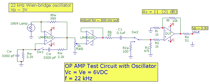
The output of the oscillator is AC coupled via C1 to the DUT noninverting (NI) amplifier circuit. Switch Sw2 provides three different
test capabilities:
- Sw2 connected to oscillator with oscillator ON: verifies NI amplifier AC performance with oscilloscope
- Sw2 connected to oscillator with oscillator DISABLED: provides a NI input DC termination of 48 kohm, for offset measurement emphasizing op amp bias current Ib
- Sw2 disconnected from oscillator and terminated with 100 ohm: provides a NI input DC termination of 1.1 kohm, for offset measurement emphasizing op amp offset voltage Vos
The gain experienced by the total DC input-referred offset for the DUT is 11 which
is, for this circuit configuration identical to the signal gain for the AC measurement.
The amplified DC total output offset voltage for the DUT is given approximately by:
Vout_offset = 11*(Vos +/- Ib[(R1+R2) - Rf || Ri] ) with the 48 kohm input termination, and
Vout_offset = 11*(Vos +/- Ib[(R2a+R2) - Rf || Ri] ) with the 1.1 kohm input termination.
where Vos and Ib are the op amp input offset voltage and input bias current respectively. (Input offset current is not included
in these simplified expressions.)
For the circuit components above, since (R1+R2) = 48 kohm, (R2a + R2) = 1.1 kohm and Rf||Ri < 1 kohm, we can approximate the
offset expressions above. Expressing Vout in mV and Ib in nA,
Vout_offset(mv) ~ 11*Vos(mV) +/- 0.5*Ib(nA) with the 48 kohm input termination, and
Vout_offset(mv) ~ 11*Vos(mV) +/- 0.01*Ib(nA) with the 1.1 kohm input termination.
For the 1.1 kohm case, bias current cancellation will occur between the NI and I inputs of the DUT. In this case the
expression approximates the worst case with a bias current OFFSET equal to the bias current itself with a 1.1 kohm load.
For FET input op amps with Ib on the order of 10 pA or less, the output offset measurement should be 11*Vos(mV), the same for BOTH switch positions.
For a bipolar op amp with say Vos = 0.5 mV and input bias current Ib of 10 nA, the contributions to output offset from Vos and Ib will
be comparable (5 mV each) for the 48 kohm termination. However, the 1 kohm termination would show half the output offset, being dominated by the Vos offset alone.
Assuming an oscilloscope with a sensitivity of ~ 0.5 mV, the circuit described here is only intended to check op amps for offset voltage (Vos) values greater than ~ 50 uV and
bias current (Ib) values greater than ~ 1 nA.
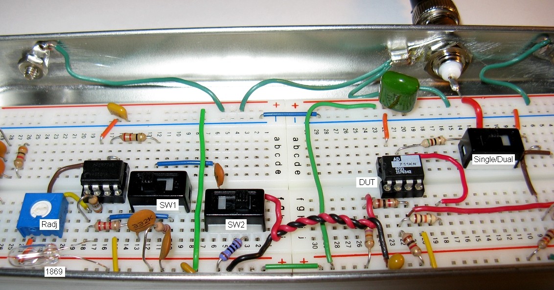
Protoboard Layout:
The layout shown below is contained in a modestly but adequately shielded 8"x3"x1" enclosure. The DUT shown is in the SINGLE op amp position. The DUAL op amp DUT
position is just to the right and uses common components R1/R2 but duplicates Rf/Ri. The SINGLE and DUAL devices are placed at different positions and only
one device can be connected during a test.
Example 1
The oscilloscope trace below show results for the AD844KN single op amp (GBW = 13 MHz, Vos = 0.25 mV; Ib = 30 pA). The measured output offset voltage,
which as expected is identical for both termination resistances, is about -1.5 mV corresponding to Vos = 0.14 mV which is consistent with the specification.

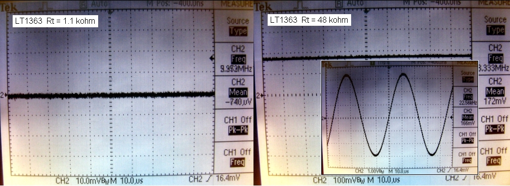
Example 2
The oscilloscope traces below show results for the LT1363 single op amp (GBW = 70 MHz, Vos = 0.5 mV; Ib = 600 nA). The measured output offset voltage for the
48 kohm termination shows a measured output offset of 172 mV corresponding to Ib_measured of 325 nA, consistent with the specification. For the 1.1 kohm termination,
the measured output offset is less than 1 mV, well within the Vos specification.
Other Ideas
Since the Wien-bridge oscillator provides an extremely low distortion sine wave output, the circuit above can be used
to monitor harmonic distortion added by the DUT in the typical 21 dB NI amplifier circuit above.
By changing the oscillator frequency to the kHz range, a good quality audio sound card can be used to monitor
the audio spectrum and view harmonic distortion products.