
Oscillators
Dec 2, 2009
Introduction:
This article demonstrates examples of Wien-bridge, LC-tuned and crystal oscillators covering the range of kHz to 100 MHz.
Wien-bridge op amp oscillators:
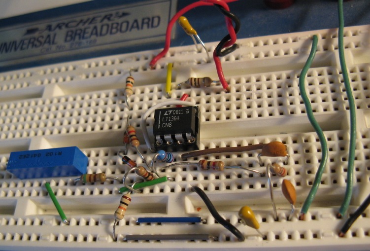
The classic super low distortion Wien-bridge oscillator with 1869 lamp stabilization and LM4562 50 MHz, 20 V/us opamp.
Useful to about 500 kHz.


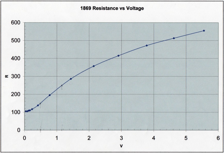
The incandescent lamp resistance as a function of DC (or RMS AC) voltage shown above can be used to determine the
peak output oscillation Vpo. The Wien-bridge phase characteristic and Barkhausen criterion requires that the
feedback resistance ratio Rf/Rlamp be exactly 2 where Rlamp is determined by the average heating effect of the
oscillation voltage across it. (This assumes that the incandescent lamp device behaves as a pure resistance at
the frequency of oscillation.)
The PEAK voltage across the lamp at oscillation is therefore Vpo*Rlamp/(Rf + Rlamp) = Vpo/3.
The corresponding RMS lamp voltage Vlamp equivalent to the DC
voltage shown in the graph above is therefore Vpo/(3*Sqrt(2)) or:
Vpo = 3Sqrt(2)*Vlamp
For example, the circuit above uses Rf=510 ohm. The lamp resistance at oscillation must be exactly half this or 255 ohm.
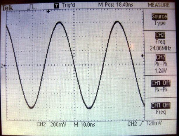
From the graph, the lamp voltage for this resistance value is Vlamp = 1.15VDC so the peak output oscillation voltage is 4.88V,
in agreement with the oscilloscope trace above.
With Rf = 300 ohm, Rlamp = 150 ohm at Vlamp = 0.5VDC and Vop = 2.1V.
With this lamp, the minimum usable value of Rf is about 220 ohm, Rlamp = 110 ohm, Vlamp ~ 0.2V and Vop ~ 0.85V.
Wien-bridge oscillator with diode limiter stabilization.
More distortion than lamp stabilization and must be adjusted to just oscillate:
To minimize diode-limiter distortion, the feedback loop is adjusted using the trimmer Rib
so that the circuit just starts to oscillate corresponding to Rf/(Ria + Rib) being slightly
greater than 3 (since the positive feedback fraction for the Wien bridge is 1/3). For 1N4148
Si diodes, the forward diode voltage just at start of oscillation is ~ 0.45 V.
The ratio of output resistors R5, R6 along with Vcc determines the output oscillation amplitude.
Simple node analysis shows that:
Vout(peak) = 3[(Vcc + Vdiode)R5/R6 + Vdiode]/(2 - R5/R6)
with Vdiode 0.4 - 0.5V.

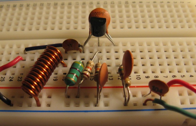
Colpitts and Clapp Transistor Oscillators:
A 24 MHz Colpitts oscillator in the common emitter configuration with high-speed 100 MHz LM6171 op-amp output buffer.
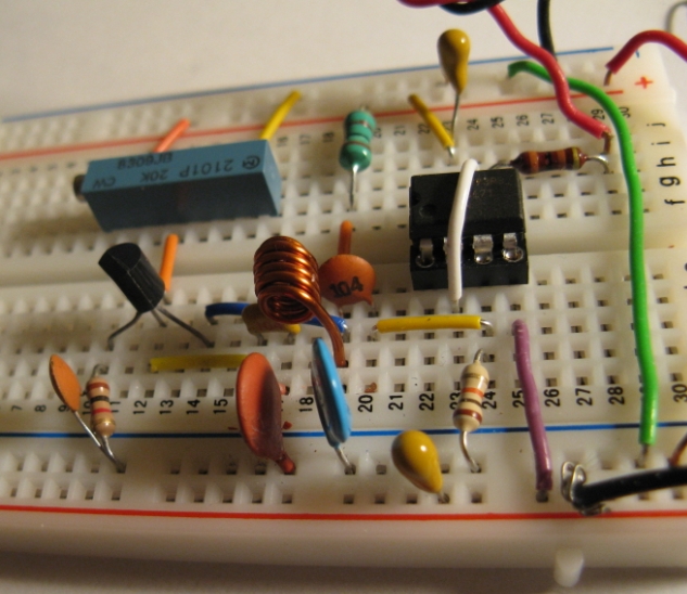

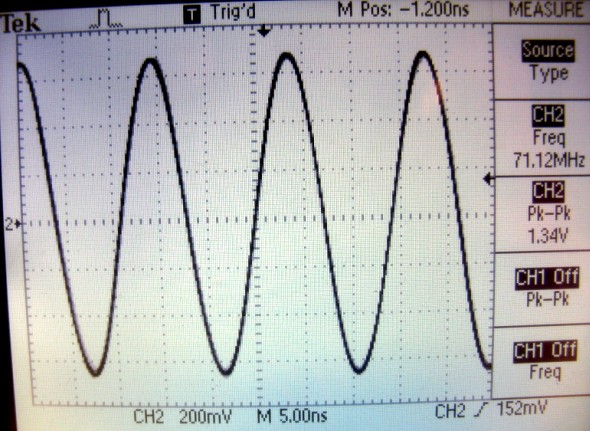
A 71 MHz Clapp oscillator in the common-base configuration. The CB configuration removes the Miller capacitance loading and bandwidth reduction
of the CE configuration enabling higher oscillation frequency. Useful up to 100 MHz:

Crystal op amp oscillator:
This circuit uses an LM6181 current-feedback op amp with a 10 MHz crystal and diode stabilization against the input op amp circuit.
Provides buffered high output drive of ~100 mA. See RF oscillator uses current-feedback op amp


References
- Sine Wave Generation Techniques, National Semiconductor Application Note 263
- Electronic Principles, A. Malvino, 3rd Edn. McGraw Hill, 1984
- Microelectronic Circuits, A. Sedra and K. Smith, 2nd Edn. Holt, Rinehart and Winston, 1987 p.724
- IC OP-AMP Cookbook, Walter Jung, 2nd Edn. 1980 SAMS.