
TIR Effects at a Lossy Incident Medium Interface
Nov 12, 2014
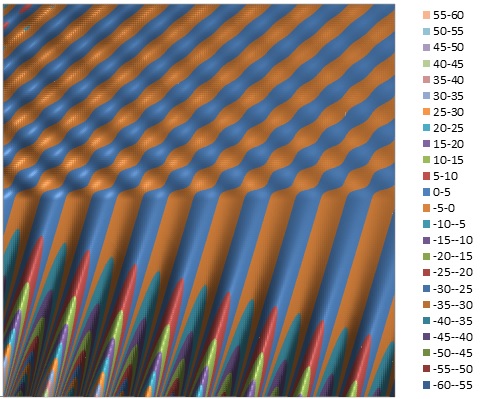
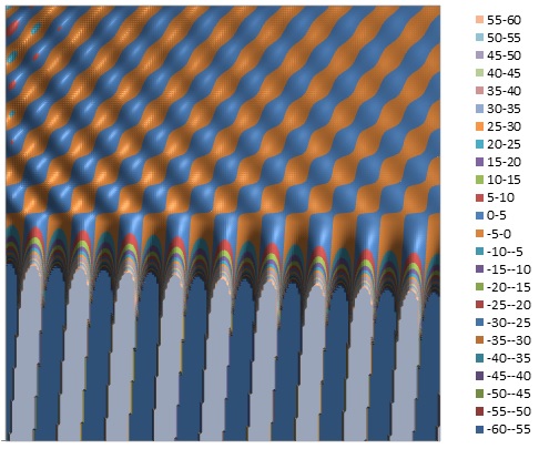
The contour plots below compare the net 2D transverse electric field profiles for an S polarized plane wave incident from the upper left
in a lossless versus a lossy medium. Plots are shown for angles less than and greater than the nominal total-internal-reflection angle (41.8° for the lossless N1=1.5 N2=1.0 interface).
The pattern in N1 (upper incident medium) is caused by interference between the incident and reflected fields. A bulk plane wave (without reflection) for the 50°
case is also shown to help visualize the incident electric field without the interference effect of the reflected wave. Note that when N1 is lossy and N2 lossless, the amplitude of the field in N2
GROWS in a direction normal to and away from the interface and the effect becomes stronger with increasing angle of incidence.
However, if N2 is lossy, at small angles of incidence,
there will always be exponential DECAY of the field in N2 in a direction normal to the interface and this complex behaviour may change to exponential GROWTH as the angle is increased.
The 2D display below maps a region of +/- four vacuum wavelengths (N2) in size with an incident field amplitude of 1.0 centered at the point x=z=0. The Ey value scale is broader for the
lossy incident case to show the larger range of field values of the incident (and refracted) attenuating field amplitude:
N1 Lossless
θ=40° N1=1.5 N2=1.0

θ=50° N1=1.5 N2=1.0 TIR

θ=50° N1=1.5 N2=1.5

N1 Lossy
θ=40° N1=(1.5 - j0.05) N2=1.0 (details)
θ=50° N1=(1.5 - j0.05) N2=1.0 TIR
θ=50° N1=(1.5 - j0.05) N2=(1.5 - j0.05)

Reference:
- Reflection at a Lossy Incident Medium Interface
- Electric Field Contour Plots
- AR Coating Calculator
- Optical Properties of Thin Solid Films, O. S. Heavens, 1965, Dover
- Thin-Film Optical Filters, H. A. Macleod, 2nd Edn., 1986, Adam Hilger Ltd., Bristol pp 28-29
- Principles Of Optics, M. Born and E. Wolf, 5th Edn. 1975, Pergamon Press, pp. 61-63
- Electromagnetic Theory, J. Stratton, 1941, McGraw Hill
- Field Theory of Guided Waves, R. E. Collin, 1991, IEEE Press
- Fields and Waves in Communication Electronics, S. Ramo, J. Whinnery, T. Van Duzer, 1984, J. Wiley & Sons