
Fields and Power
Nov 14, 2014
A plane wave is reflected at the interface between two homogenous, isotropic, semi-infinite and possibly absorbing media N1 and N2 where absorption is
represented by a negative imaginary part of N1 or N2. (N as used below will refer to either N1 or N2):

The plane of incidence is the XZ plane in the orientation shown below. The media interface is the plane X=0:

Within N1, all field vector components have the common factor for the incident and reflected wave respectively:
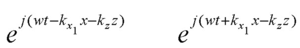
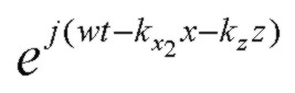
and in the exit medium N2 all field vector components have the common factor:
where we can write the complex propagation constant vector for medium 1 or 2 as:

The components of the propagation constants kx and kz may be complex depending on the values of N1 and N2 and the angle of incidence.
Exponential decay is represented by a negative imaginary part of a propagation constant in the exponential sign convention used here. Note that it is possible to
have exponential GROWTH in the +x direction normal to the layers under some circumstances with loss in the incident medium.
Although there may be loss in the incident medium N1,
we will assume that the incoming incident plane wave is a homogeneous plane wave with phase and amplitude planes being parallel. This
also means that the angle of incidence is a well defined real angle θ.
Continuity along the interface X=0 requires that kz has the same value in both N1 and N2 (Snell's law).
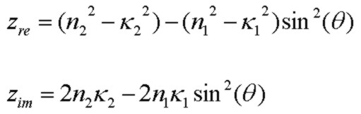
The normal components of propagation constant are then


where:
Field Components
For an S (TE) polarized wave with Ey being the only nonzero electric field component of E, one of the Maxwell curl equations as appropropriate for plane waves as described above
can be used to obtain the H vector field components in terms of the complex components of k in that region:


For a P (TM) polarized wave with Hy being the only nonzero magnetic field component of H, another of the Maxwell curl equations
can be used to obtain the E vector field components in terms of the complex components of k and refractive index in that region:
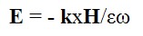

where all loss effects (including any conductivity) can be represented by a complex dielectric constant ε or a corresponding complex refractive index where ε = N2.
Poynting Vector: Single Wave
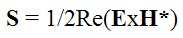
The time-averaged power flow for a single time-harmonic plane wave propagating in a medium of refractive index N, for example the refracted wave in medium N2 in the interface geometry above,
is given by the Poynting vector:
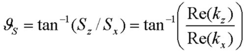
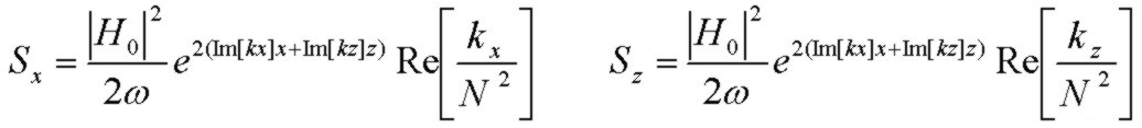
For an S (TE) polarized wave, the components of the Poynting vector are:

and using the field expressions above:

The Poynting vector for S polarization thus makes an angle with the normal to the interface of:
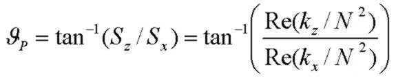
For the P (TM) polarized wave, the components of the Poynting vector are:

and using the field expressions above:
The Poynting vector for P polarization makes an angle with the normal to the interface of:
Stratton (1941, pp. 500 - 510) contains an interesting discussion of propogation direction and material properties in a conducting medium at optical and radio frequencies.
E0 and H0 above are the complex scalar field amplitudes of the wave at X=Z=0. Exponential decay is represented by a negative value for the imaginary part
of kx or kz.
As applied to the two medium interface geometry above, if N1 is real (non-absorbing) and N2 is complex (absorbing), kx will always be negative. However, if N1 is absorbing, then
kx in medium 2 may be positive representing an exponentially growing field. The expressions above apply to a general single plane
wave which may be inhomogeneous. However, a LOSSY incident medium with a combination of incident and reflected waves, as described in the next section, does not allow for a simple flux separation
in terms of Poynting vectors of the separate waves (as represented in expression above) so that a simple power balance involving "separate" wave powers is not possible i.e. R + T = 1 (Macleod 1986).
However, the normal component of Poynting vector calculated from the TOTAL field is continuous across an interface as required by energy conservation.
Poynting Vector: Incident + Reflected Wave
Power flux continuity applies across an interface in terms of the normal (X) component of Poynting vector provided the total E and H fields (incident plus reflected) are used. Proceeding as above
and remembering that the kx component of propogation constant is reversed for the reflected wave compared to the incident wave, we can easily derive the X component of the
Poynting vector in region X<=0 with refractive index N.
For S polarization (TE):

where r is the Fresnel interface reflection coefficient for Ey. At the interface X=0, Sx represents the normal component of power flux into the interface (from N1 to N2):

This value will be exactly equal to the power flux computed above for the SINGLE wave in N2, where, for a unit E0 or H0 in the incident medium,
the amplitude of the wave in N2 is t, the Ey (or Hy) transmission coefficient as given by the Fresnel equations.
Applying exactly the same analysis, the results for the P polarization (TM) are:

where rH is the Fresnel reflection coefficient for Hy. At the interface X=0, Sx again represents the normal component of power flux into the interface (from N1 to N2):
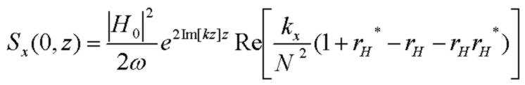
Note that in all the expressions above for Sx, if there is loss in the incident medium N1, kz will be complex and Im[kz] will be negative.
and therefore, for all nonzero angles of incidence, Sx will exponentially decay with Z along the interface.
However the local power balance (at any given Z value) across the interface still applies.
The expressions above provide a good power-balance "sanity check" in reflectivity solvers in cases where there is loss in either or both media.
Fresnel Interface Reflection and Transmission Coefficients
(Note: in the expressions below, n1 and n2 are the full complex indices equal to N1 and N2 as used above)
The electric field Fresnel interface reflection and transmission coefficients for S polarized (TE) are:

and for P polarization (TM) and with vector direction chosen so that rs and rp are identical at normal incidence:

For the P polarization, it is convenient to use the Hy reflection and transmission coefficients (as used above in the Poynting vector expressions):
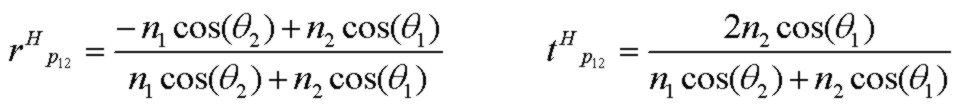
The Fresnel reflection coefficients above can easily be written in terms of the normal component of propogation constant, kx in N1 and N2 instead of the (complex) angles above.
Reference:
- Reflection at a Lossy Incident Medium Interface
- Absorbing Film Optical Properties
- AR Coating Calculator
- Electric Field Contour Plots
- Optical Properties of Thin Solid Films, O. S. Heavens, 1965, Dover
- Thin-Film Optical Filters, H. A. Macleod, 2nd Edn., 1986, Adam Hilger Ltd., Bristol pp 28-29
- Principles Of Optics, M. Born and E. Wolf, 5th Edn. 1975, Pergamon Press, pp. 61-63
- Electromagnetic Theory, J. Stratton, 1941, McGraw Hill
- Field Theory of Guided Waves, R. E. Collin, 1991, IEEE Press
- Fields and Waves in Communication Electronics, S. Ramo, J. Whinnery, T. Van Duzer, 1984, J. Wiley & Sons