
Reflection at a Lossy Incident Medium Interface
Nov 12, 2014
I wish to acknowledge and thank
H. A. Macleod
for his extensive technical conversations and assistance in understanding and
providing valuable insight into this topic.
This note discusses plane wave reflection at an interface in which the incident medium is lossy.
External Reflection Case:
 The external reflection case (N1 < N2) doesn't involve a "total internal reflection" effect, is easier to understand and therefore is discussed first.
(The conventions and formal mathematical expressions used are shown in the next section).
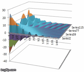
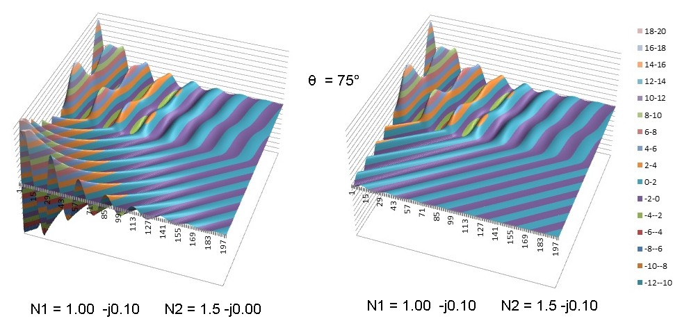
The first contour plot below and the time animation at right show the computed transverse real electric field amplitude profile Ey(x,z) for a TE (s) polarized plane homogeneous wave,
incident from the upper left within an isotropic lossy medium with a complex refractive index N1 = 1.0 -j0.1 at an incident angle of 75 ° into a lossless glass-like medium N2 = 1.5.
In the incident medium, the plane wave has a complex propagation constant K1 = k0*N1. This incident plane wave is assumed homogeneous
with the planes of equal phase and amplitude being parallel (this is the usual homogeneous plane wave usually discussed in infinite
conducting media) and the power flow is in the direction normal to these planes. The electric and magnetic fields are orthogonal (for s or p pol. incident waves) and also the field vectors in the incident wave are
at right angles to the direction of propogation but will differ in phase due to the loss in N1 as described by the complex propogation constant K1. As pointed out by Macleod (1986), it is NOT possible to separate the net
field in a lossy medium with incident and reflected fields into separate power flow beams with well defined power densities (Poynting vectors) such that (R + T) = 1 due to field coupling in the
net Poynting vector expression at the interface. (This is possible in any incident medium without loss).
Nevertheless, the complex field amplitude reflectivity and transmissivity can be computed properly as done below using the usual complex Fresnel expressions.
The ripples in the incident medium are due to interference between the incident and partially reflected field.
The refracted wave is inhomogeneous and the equiphase planes are at right angles to those of equal amplitude.
This very simple example demonstrates that, in the final medium (N2), the component of propagation constant NORMAL to the layers in the x direction, kx2
does NOT always show exponential decay away from the interface, an assumption typically made in multilayer reflectivity
problems with absorbing media. In fact, in this very simple example the amplitude of Ey INCREASES moving into N2 in the x direction. This is clearly seen as
a consequence of the plane wave attenuation in N1, along with transparency in N2. Qualitatively, refraction at "earlier" z points along the interface have locally higher amplitude,
and are refracted and propagate in the lossless exit medium as shown. The second plot below shows that if we introduce loss into N2, the
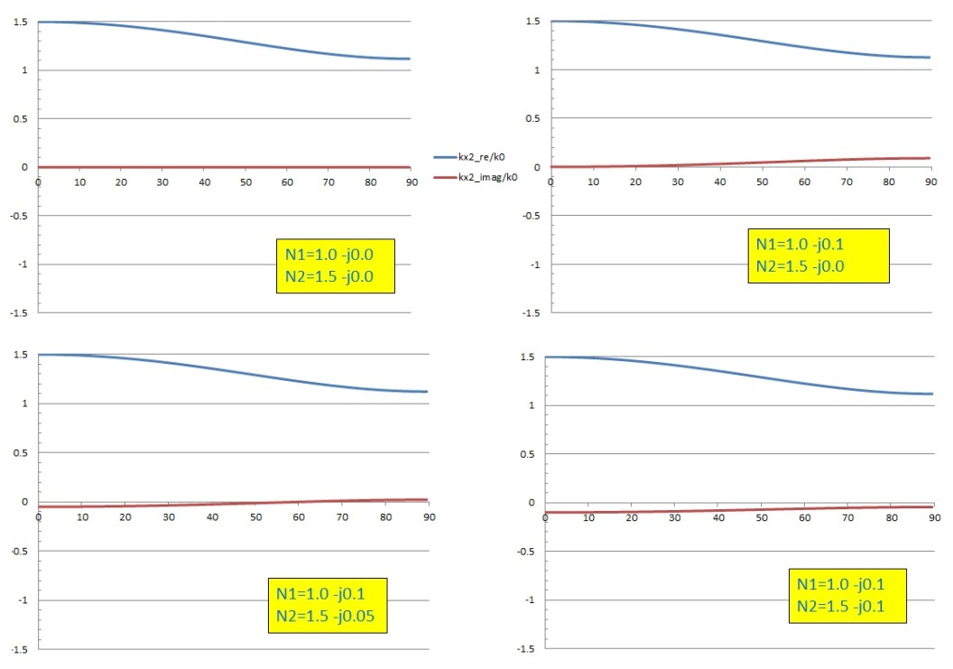
field in N2 can transition to an exponential decay as shown. In fact with fixed loss in N1 and N2, it is possible to have a continuous change from exponential decay (always true
at normal incidence if there is loss in N2) to exponential growth with angle. This is demonstrated in the series of normalized kx2/k0 versus angle graphs below where the value of loss in N2 is increased.
The change in form and value of kx2_imaginary, which represents amplitude variation normal to the layer, with (+/-) values corresponding to (growth/decay) in N2, is clearly evident:
The external reflection case (N1 < N2) doesn't involve a "total internal reflection" effect, is easier to understand and therefore is discussed first.
(The conventions and formal mathematical expressions used are shown in the next section).
The first contour plot below and the time animation at right show the computed transverse real electric field amplitude profile Ey(x,z) for a TE (s) polarized plane homogeneous wave,
incident from the upper left within an isotropic lossy medium with a complex refractive index N1 = 1.0 -j0.1 at an incident angle of 75 ° into a lossless glass-like medium N2 = 1.5.
In the incident medium, the plane wave has a complex propagation constant K1 = k0*N1. This incident plane wave is assumed homogeneous
with the planes of equal phase and amplitude being parallel (this is the usual homogeneous plane wave usually discussed in infinite
conducting media) and the power flow is in the direction normal to these planes. The electric and magnetic fields are orthogonal (for s or p pol. incident waves) and also the field vectors in the incident wave are
at right angles to the direction of propogation but will differ in phase due to the loss in N1 as described by the complex propogation constant K1. As pointed out by Macleod (1986), it is NOT possible to separate the net
field in a lossy medium with incident and reflected fields into separate power flow beams with well defined power densities (Poynting vectors) such that (R + T) = 1 due to field coupling in the
net Poynting vector expression at the interface. (This is possible in any incident medium without loss).
Nevertheless, the complex field amplitude reflectivity and transmissivity can be computed properly as done below using the usual complex Fresnel expressions.
The ripples in the incident medium are due to interference between the incident and partially reflected field.
The refracted wave is inhomogeneous and the equiphase planes are at right angles to those of equal amplitude.
This very simple example demonstrates that, in the final medium (N2), the component of propagation constant NORMAL to the layers in the x direction, kx2
does NOT always show exponential decay away from the interface, an assumption typically made in multilayer reflectivity
problems with absorbing media. In fact, in this very simple example the amplitude of Ey INCREASES moving into N2 in the x direction. This is clearly seen as
a consequence of the plane wave attenuation in N1, along with transparency in N2. Qualitatively, refraction at "earlier" z points along the interface have locally higher amplitude,
and are refracted and propagate in the lossless exit medium as shown. The second plot below shows that if we introduce loss into N2, the
field in N2 can transition to an exponential decay as shown. In fact with fixed loss in N1 and N2, it is possible to have a continuous change from exponential decay (always true
at normal incidence if there is loss in N2) to exponential growth with angle. This is demonstrated in the series of normalized kx2/k0 versus angle graphs below where the value of loss in N2 is increased.
The change in form and value of kx2_imaginary, which represents amplitude variation normal to the layer, with (+/-) values corresponding to (growth/decay) in N2, is clearly evident:
Internal Reflection Case:
The case with internal reflection, which exhibits a discontinuous TIR effect for lossless media is less intuitive and demonstrates some interesting features not seen in the
external reflection case above.
With the plane of incidence the xz plane and x being normal to the interface, the exponential convention used here is:

In the example above, the field in the x direction normal to the layers will exponentially increase into medium N2 for ANY angle of incidence, if medium N2 is lossless.
However, if medium N2 is lossy, the field amplitude in N2 may exponentially grow or decay depending on the relative values of complex refractive index N1 and N2 and
the angle of incidence, as in the external reflection case above:

and both real and imaginary parts of the indices affect this behaviour. As the angle is varied, the real or imaginary part of kx2 will have a zero crossing, as seen in the curves below, at
an incident angle θz given by (provided a real angle exists, i.e. n2κ2/(n1κ1) <1):

The behaviour is somewhat complex and nonintuitive. To show the range of possible behaviour, the graphs below show the real (blue) and imaginary (red) parts of kx2 versus angle of incidence
as the loss of N2 is varied with the loss in the incident medium held fixed. The transition from a zero crossing for the imaginary part of kx2 (similar to the external reflection case) to a zero crossing for the REAL (phase parameter)
part of kx2 is determined by the condition below for a full complex zero of kx2:
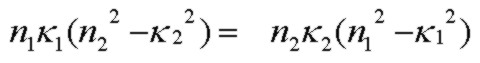
Note that if N1 and N2 satisfy this exact zero condition for kx2, the wave in N2 will be a simple homogeneous attenuating plane wave moving exactly in the z direction parallel to the interface with
a fixed amplitude (zero decay or growth) extending infinitely far into N2, exactly like the well-known TIR angle for lossless media. In this case, the S (and P) reflectivity will be exactly 1.0 and the
power flow into N2 normal to the interface is exactly zero.
A contour plot of this is shown below:

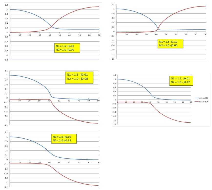
For perspective, the graph below shows kx2 for the lossless case with a total internal reflection angle of 41.81°. With loss in N1 and/or N2, there is no true "total internal reflection"
at any angle for the two region interface, but the graphs above show that the rapidly changing structure in kx2 is close to the lossless TIR angle. In a sense, loss in N1 or N2 "washes out"
the sharpness of the TIR angle effect, similar to classic resonant behaviour damping.

Mathematical Detail:
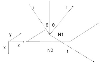


and assuming a homogeneous lossless plane wave in N1, θ is a real angle of incidence:

The standard complex square root (with positive or zero real part) is:

The alternate root is the negative of that above.
There may be a zero crossing at some angle of incidence in either the real or imaginary part of kx2, depending on the complex values of N1 and N2.
A zero crossing will exist if there is a real angle such that Zim=0, i.e. :

at an angle:

By inspection of the complex square root expression above, the zero crossing will occur for kx2_real if Zre is negative at the zero angle condition above:
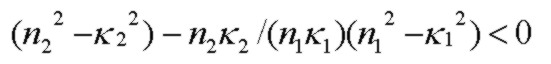
and the zero will occur for kx2_imag if the expression is positive. A full zero in kx2 (i.e. a simulaneous zero in both kx2_real and kx2_imag) will occur if the expression above is identically zero.
Reference:
- Fields and Power
- Absorbing Film Optical Properties
- AR Coating Calculator
- Electric Field Contour Plots
- Optical Properties of Thin Solid Films, O. S. Heavens, 1965, Dover
- Thin-Film Optical Filters, H. A. Macleod, 2nd Edn., 1986, Adam Hilger Ltd., Bristol pp 28-29
- Principles Of Optics, M. Born and E. Wolf, 5th Edn. 1975, Pergamon Press, pp. 61-63
- Electromagnetic Theory, J. Stratton, 1941, McGraw Hill
- Field Theory of Guided Waves, R. E. Collin, 1991, IEEE Press
- Fields and Waves in Communication Electronics, S. Ramo, J. Whinnery, T. Van Duzer, 1984, J. Wiley & Sons