
Absorbing Film Optical Properties
Nov 12, 2014
The plots below show the optical reflectance, transmittance and coefficient of reflection and transmission phase angles for a single absorbing layer with a plane electromagnetic wave
incident from a real-index medium with angle of incidence θ1. The conventions used for the calculations (color plots below) are:
- exponential propagation factor exp(j[wt - kx]). With this convention, a medium with loss is specified with a complex refractive index having a NEGATIVE imaginary part.
- E-field reflected vector direction for TM (p) case chosen so that rs = rp at normal incidence
[These conventions correspond to those of O. S. Heavens, "Optical Properties of Thin Solid Films", Dover 1965. In contrast, Born and Wolf, "Principles of Optics" 5th Edn. 1975 uses the opposite exponential
convention of exp(j[kx - wt]) and a TM reflected E-field sign convention with rs = -rp at normal incidence.
With the Born and Wolf convention, a medium with loss is specified with a complex refractive index having a POSITIVE imaginary part. The convention used of course cannot effect the physical results, so reflectance
and transmittance will be identical, but the phase values will be different in sign and with an offset of π radians depending on the convention. In multilayer calculations, it is important to be consistent and use
a fixed set of conventions.]
The interface Fresnel reflection and transmission coefficients below, rs ts for TE with E field perpendicular to plane of incidence,
and rp tp for TM with E field parallel to plane of incidence, and the corresponding results for a single film (two interfaces) are general and are valid for arbitrary complex indices
and angles of incidence where the refracted angles in the media may be complex. In this case, the appropriate complex root must be chosen to describe the
component of field propagating normally away from the film. A calculator facilitates checking results for the common single layer configuration.

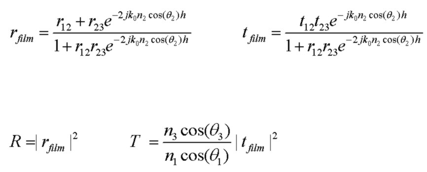
where the expressions the 3 region single film are valid for both TE (s) and TM (p) polarizations, with the polarization differences encapsulated in the r12, r23, t12, t23 values. For a nonabsorbing film, R + T=1.
If the incident medium is lossy, it is not possible to define reflectance and transmittance values such that R + T = 1 due to field coupling in a lossy medium (MacLeod 1986).
Note that using the E-field vector sign convention above for the TM case, the reflection coefficients rs and rp are identical at normal incidence θ=0°. The actual sign of rs and rp for normal incidence will be reversed if N1 and N2
are interchanged ("internal" verses "external" reflection). However it is easy to show using the interface Fresnel reflection coefficient expressions above that at θ=90° glancing angle of incidence, the reflection coefficients rs and rp are completely
independent of the complex N1 and N2 values and, with the sign convention used above it is found that rs(θ=90°) = -1 and rp(θ=90°) = +1 and also ts=tp=0 at θ=90°.
The only exception to this is obviously if N1 and N2 are exactly the same in which case obviously rs=rp=0 and ts=tp=1.0. These results for θ=90° are also true for any multilayer sequence as can
be verified by analyzing the 3 region expression above with r12 being the upper interface Fresnel reflection coefficient.
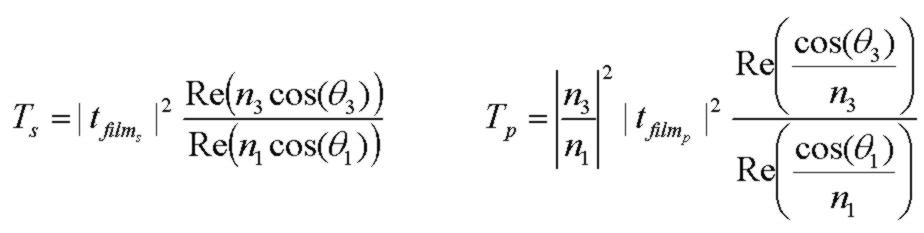
If the final medium has loss, but the incident medium is lossless, R and T values are well defined and (R + T) =1 . However, the transmittance expressions are more complicated and different for S and P polarizations. The following expressions
apply to any angle, including TIR angles, and for any complex indices n2, n3 with the understanding that θ3 may be complex as
determined by the general form of Snell's law above.
If n1 and n3 are real (no loss), the general expressions below for Ts and Tp reduce to the simpler result above, even if n2 is complex:
Macleod (1986) provides alternate expressions for Ts and Tp, based on wave admittances, that are fully equivalent to the general expressions above. Note
that Macleod defines the reflection coefficient differently with tp for the TM case in terms of the E-field component ALONG the interface, thereby including
the angular factor (for power per unit area normal to the surface) in the definition of tp.
The rfilm and tfilm expressions above may be used in a fast iterative procedure to calculate reflection and transmission coefficients for an arbitrary number of
layers with loss, as given by P. Rouard (1937) and described in O. S. Heavens (1965). This algorithm is equivalent to use of the well known characteristic matrix and other similar
approaches, but is, in my opinion, more intuitive.
Note: For the P polarized (TM) case, it is sometimes convenient to use the Fresnel reflection and transmission coefficients for the Hy field (e.g. Stratton 1941).
This is fully equivalent to use of the rp and tp E field coefficients above but the expressions are different, particularly the tpH value:

Example:
Normal Incidence Theta = 0 deg

Born & Wolf "Principles Of Optics" 5th Edn. 1975 p. 631
Note: n2 = 3.5( 1 + j0.1) where k2 = 0.1 in B&W notation
Reflectance, Transmittance and Phase Angles (rad) versus angle of incidence (deg)
Fixed t2 = 0.222 um

Reference:
- Optical Properties of Thin Solid Films, O. S. Heavens, 1965, Dover
- Thin-Film Optical Filters, H. A. Macleod, 2nd Edn., 1986, Adam Hilger Ltd., Bristol.
- Principles Of Optics, M. Born and E. Wolf, 5th Edn. 1975, Pergamon Press, pp. 61-63
- Electromagnetic Theory, J. Stratton, 1941, McGraw Hill
- Field Theory of Guided Waves, R. E. Collin, 1991, IEEE Press
- Fields and Waves in Communication Electronics, S. Ramo, J. Whinnery, T. Van Duzer, 1984, J. Wiley & Sons