
WaveMon
March 05, 2009

WaveMon is a Windows application that monitors the PC soundcard line-in signal and acquires statistics
on the sampled input signal. It can be easily adapted to low-frequency pulse counting tasks and experiments.
WaveMon currently supports two fixed sampling conditions:
- 44.1 kHz / 16 bit stereo with 12 kb sampling buffers
- 96.0 kHz / 24 bit stereo with 36 kb sampling buffers
For each channel, WaveMon displays:
- RMSb: the rms value, averaged over the current buffer samples
- Maxb: the maximum sample absolute value for the current buffer
- MAX: the maximum sample absolute value for the entire current recording
- Trig: the most recent sample trigger value that incremented the count
- Count: the total counts accumulated as determined by the trigger settings
- dT the time interval between the two most recent trigger counts
- graphical dB level meters with a range -120 to 0 dB
- accurate RMS and Peak dB values
- RMS voltage level in mV, provided the input sensitivity is calibrated
The user configurable settings are:
- Sampling Rate (default is 16 bit, 44.1 kHz)
- Count Time (default is 10,000 sec ~ 2.8 Hrs)
- Trigger Level (default is 10,000)
- Trigger Holdoff (default is 1000 ms)
- Full-scale calibration voltage (default is 2.0 V)
WaveMon displays the start and stop local date and time of the recording as well as the running total elapsed time
since the start of recording. At the end of recording, as determined by either the Count Time expiring or the user clicking End,
the total number of Bytes and data Buffers read is displayed
at the bottom along with the calculated effective byte sampling Rate in bytes/sec.
A summary of the displayed data in the WaveMon
window can be saved to a text file with the Store button. The file is saved in the same directory as
the WaveMon.exe application with a name WaveMon_datetime.txt, for example:
WaveMon_WedFeb182009083303.txt
The Count number tracks the total trigger counts for each channel. The same trigger level and holdoff is used for each channel.
The trigger level is entered in sample units and is also displayed as a dB value.
With a low noise sound card with a typical line-in sensitivity of 1 V, audio signal pulses down to about 50 microvolt amplitude can be counted.
Sampling rates of 44.1 and 96 kHz correspond to sampling intervals of 22.5 and 10 microseconds respectively.
Assuming a reasonably good sound card and a typical pc, (e.g.> 500 MHz PIII WinXP+ 125 Mb RAM) WaveMon can capture and count
pulses down to about twice the sampling interval with proper adjustment of trigger level and trigger holdoff.
Display Units
The rms and maximum data values displayed in the sample data lines for each channel are absolute values of the digital signal amplitude which for standard 16 bit
signed integer sampled conditions is in the range 0 - 32,768 and for higher resolution 24 bit signed integer sampling is in the range 0 - 8,388,608.
The relationship between these values and the actual input signal level in volts depends on the sound card full scale "sensitivity" as well as
the configuration of the input mixer settings such as line-in level, recording level etc. If required, the user can perform an absolute calibration
using accurate AC sources connected to the line-in connector as discussed below.
The dB level meters for left (green) and right (red) channels are below the corresponding sample data lines.
The dB level meter displays the RMSb value relative to the RMS value of a full scale sine wave for that sample rate,
e.g.:
20*Log10(RMS_b/(0.707*32767))
for 16 bit sampling. A full signal sine-wave will therefore display as 0 dB on this meter.
The corresponding numerical dB RMSb value is displayed below the graphical dB level meter, followed by the peak dB value for the buffer
corresponding to the Maxb value, e.g.
20*Log10(Maxb/32767)
for 16 bit sampling. Note that for pulse signal widths considerably shorter than the buffer time of ~ 70 ms, Maxb/RMS_b >>1
so large differences can be expected under these conditions for the displayed dB values.
For continuous sine wave signals the amplitude ratio Maxb/RMSb = 1.414 and these two dB values are equal.
For continuous random noise, the amplitude ratio Maxb/RMSb will be 3 to 5 due to the noise crest factor
in which case the dB values will differ by 7 - 14 dB.
To the right of the numerical dB values is displayed the input RMS voltage in mv. The voltage displayed will be accurate
if the voltage range is calibrated as discussed below.
The time interval between most recent consecutive trigger counts is displayed to the right of the voltage values, accurate to about 10 microseconds.
Using WaveMon
WaveMon can be used to simply monitor audio-band input signals and noise directly without using the counting feature.
To monitor an input signal, open the sound mixer (Microsoft's Sound Control panel or any 3rd party installed mixer),
select the Recording settings and select the line-in source. Connect some "line-level" source (~ 1V or less) you wish to monitor to the
line-in jack of your sound card, typically a 1/8" stereo minijack connection. Start WaveMon and click Record,
adjust the line-in (or "Recording") level in your sound mixer and view the updated channel data display (Left and Right data lines)
in WaveMon. The display is continuously updated after each buffer is analyzed at intervals of about 70 ms (44.1 kHz) and 64 ms (96 kHz).
The Reset button is active during recording and resets the counts, maximum sample values and the last triggered
count sample value in the recording, while recording continues. The Reset button does not read new trigger settings nor does
it reset the time counters or the total bytes and buffers counted.
Additionally, WaveMon can be used to check the background noise level of your sound card. With no line-in connection,
ideally the RMSb level displayed should be <2 (44.1 kHz) and <100 (96 kHz), corresponding to noise at least -85 dB down from the full signal level.
As a benchmark, a typical line-in connection with an input impedance of 10 kohm at room temperature would contribute about 2 microvolt RMS
thermal noise in a 20 kHz noise bandwidth implying a limiting S/N ratio of about 114 dB.
A high quality sound card will have a total input noise voltage of less than 10 microvolt total, with some noise
contributions from internal amplifier noise which for an input sensitivity of 1Vrms corresponds to a S/N ratio of about 100 dB, with lower cost
good quality retail sound cards achieving S/N ratios of 80 - 90 dB.
Move the line-in slider to check the
quality of your sound card. Poor quality cards usually show noise spiking *while* the slider is being moved. Audio recording software included
with sound cards usually features a rudimentary "level meter" display which typically is low resolution. WaveMon displays high resolution
numeric information of the digitized data. For monitoring weak signals, it is fairly easy to assemble a preamplifier using standard opamps
with low noise and sufficient bandwidth. LED optical pulse counting below shows a simple example.
Voltage Calibration
In order to display correct signal (and noise) absolute voltage levels with WaveMon, the line-in "sensitivity" must be calibrated. The default
value of 2.0 volts is typical of some sound cards with typical mixer input levels, but basic calibration is required to ensure accuracy.
The input voltage level required to achieve full scale (FS) digital signal depends on the intrinsic sensitivity of the sound card as well as the line-in
mixer level settings.
WaveMon provides a single calibration point and assumes equal sensitivity of both stereo channels. The suggested procedure for calibration is:
- set the mixer so that only the line-in is active with all other input sources muted
- set any input mixer settings, which might be labeled as "RECORD LEVEL", "MASTER LEVEL", to fixed settings.
Typical examples are MASTER IN level = 100% LINE-IN level = 0 dB (usually marked as 50%).
- connect a pure sine-wave source with a variable amplitude to the line-in connector. ENSURE that the maximum voltage level of the sound card
is not exceeded (typically ~ 2V)! The frequency of the source should be within the audio
passband, say 50 Hz to 15 kHz. Increase the input level until FS signal is reached (0 dB). Measure the PEAK voltage of the sine wave and enter
this value into the VFS field of WaveMon.
The displayed RMS voltages (in mVrms) which are obtained from the displayed RMSdb values will now be reasonably accurate assuming the sound card is linear.
When WaveMon is used and accurate voltage levels are required, the mixer should be checked to verify that the input level settings haven't changed.
Counting Events
Sound cards are designed for recording and playing audio frequencies between about 20 Hz to 20 kHz. The ability to resolve temporal sound details
depends on the sampling rate. WaveMon supports the standard CD-DA rate of 44,100 Hz at 16 bit detail as well as the high quality rate of 96 kHz
at 24 bit detail (if your sound card supports it). Both these sampling rates provide adequate coverage of the audio bandwidth. Audio frequency pulses or noise bursts
in this range can then be detected and, with suitable trigger settings, "counted".
WaveMon implements a rudimentary ability to capture and count "audio pulses". To achieve this, one must have a
rough idea of the minimum time between the "audio events" or "pulses" that one wishes to count.
To count such "pulses",
- connect the source to be counted to the line-in connector
- adjust the line-in/recording setting in the sound mixer to a suitable level that does not cause distortion
- manually check that the Trigger Level setting is low enough to trigger counting; if necessary, lower the Trigger Level
- set the Trigger Holdoff setting (for example 7.5 ms) to a value slightly less than the minimum time between the audio pulses you wish to count
- set the Counting Time (in seconds) to the total time you wish to count
- start Recording
When Record is started, the Time, Counts and Max values are zeroed. WaveMon does not store or save cumulative buffers of data but simply processes the buffers
"on the fly", acquires statistics and releases the buffers for reuse.
Example: Counting LED Pulses
As a fairly simple example of pulse counting, a red LED was pulsed using an LM3909N flasher IC producing optical pulses of about 8 ms duration at a rate of 1 Hz:

A Si photo detector with a 50 ohm load followed by a simple 40 dB (X100)
gain stage preamplifier was used to detect and amplify the 100 microwatt-level LED optical flashes.
The sound card was a Creative Technologies Audigy 2ZS Notebook device. The photo detector can be seen
below beside the IC on the protoboard. A shielded stereo RCA plug to 1/8" stereo miniplug cable was used to connect the amplifier to the line-in jack. Only the right channel was
connected to the amplifier. The bandwidth of the photo detector and amplifier combination is DC to 5 MHz and therefore is not a limitation in the measurement:

The line-in record level was set at 0 dB which provides a sensitivity of 2.0V peak for a full amplitude recorded digital signal.
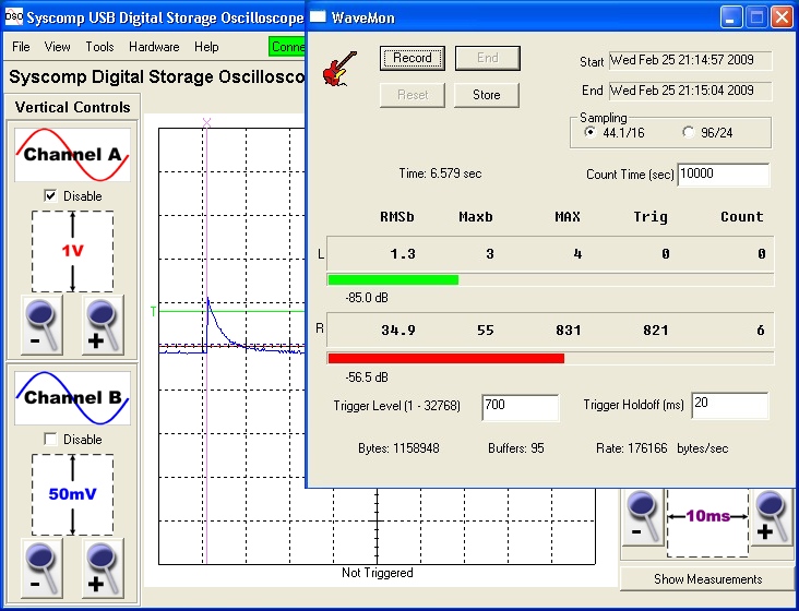
The LED pulses have rapid rise times and slower decay times as shown below. Pulses were checked to see variability of pulse amplitude using
WaveMon and a suitable trigger level was easily determined to be ~ 700 corresponding to a received line-in electrical pulse amplitude of about 65 mV peak consistent
with the input sensitivity. Using the Reset button during setup facilitates configuring the best trigger settings.
A 20 ms Trigger Holdoff ensures that secondary triggering does not occur during the same optical pulse. The image below shows the settings in WaveMon
as well as the actual electrical pulse input at the line-in connection as monitored with a Syscomp Electronic Design
DSO-101 3 MHz BW USB digital oscilloscope.
The pulse counting accumulates counts on the right channel only.
Because the line-in connection of most sound cards is AC coupled, it is interesting and instructive to examine the actual sampled pulse data in the cumulative
buffer data. This was achieved by recording a few seconds of the pulse data input using another basic sound recording utility. The resultant digitized data plot below
shows the ~ 10 ms pulse with an undershoot, representing the AC decoupling of the sound card input.
Since we are using a Trigger Holdoff significantly longer than this decoupling "recovery time", it does not affect the measurement in this case, but is important
to understand.

Note that since sound cards have no DC response, the average DC level for a sampled and digitized pulse train will be zero.
Therefore a line-in positive-going electrical pulse of say 200 mV peak level with a zero-voltage baseline
and a duty cycle of say 5% will have a digitized undershoot of 200*5/95 or about 11 mV.
WaveMon has been tested with pulse sequences as short as 50 microseconds and in this case, accurate counting can be obtained
under either 44.1 kHz or 96 kHz rates. A sample image of such a pulse, captured at 96 kHz sampling rate and showing about 5 samples
during the pulse is shown below:

Sound Cards Tested:
WaveMon has been tested on the following two Creative sound cards:
- SoundBlaster Audigy 2ZS PCMCIA Notebook card
- SoundBlaster Audigy 2ZS Platinum Pro
Both these cards represent good quality and moderately priced sound cards with S/N levels below 85 dB. For basic pulse-counting
applications as described above, generic inexpensive sound cards included with most computers may be satisfactory depending
on the signal amplitude being measured and the associated background noise. It should be easy to determine with some quick
tests if the available sound card can be used for the purposes at hand. Notably, laptop computers with built-in sound cards and line-in
jacks can be very useful for portable pulse counting applications.
Performance Notes:
Since Windows is a multi-tasking and not a real-time operating system, it is possible that depending on the other processes running on the
computer, there potentially could be occasional interruptions in the sampling. For counting applications requiring high reliability, dedicated
counting hardware should be used. For extended counting times (say over several hours) it is advisable to stop non-critical processes on
the computer and elevate the process priority of WaveMon in the task manager to help mitigate any counting interruptions. Preliminary
testing of counting accuracy over the expected measurement time period is recommended.
Application Details:
The application is written in C and uses the Windows low-level waveform audio input API waveInxxx.
This application is based on the Petzold's Digital Sound Recorder sample from Programming Windows 5th Edn., 1999 Microsoft Press.
The memory reallocation in the original Petzold example was removed and
the waveform data buffers are processed and analyzed as received via the MM_WIM_DATA message in the DialogBox procedure.
Two waveform sampling data buffers are used for each sampling mode.
64 bit integers (19 digits in size) are used to store trigger counts and bytecounts which ensures that no overflow will ever occur
and that timing measurements for trigger holdoffs are accurate even over long time intervals. The QueryPerformanceCounter() function is used
for accurate timing calculations returning results typically better than 50 microseconds with a modest processor.