
A Note On Phase Margin
Aug 09, 2012
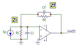
The feedback properties of an op-amp circuit determine the circuit stability. In the simplest scenario, a fraction β of the output signal is
passed back to the inverting (INV) input using a voltage divider network as shown in the current-to-voltage transimpedance Tz circuit.
In general, the voltage divider network will consist of complex impedances meaning that the feedback signal will have a frequency dependence in
both amplitude and phase.
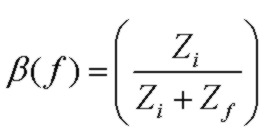
Assuming that the op-amp input impedance at the INV input is extremely high and no current is draw by the INV input, the voltage feedback fraction β at the INV input is:
The Noise Gain function is defined as the inverse of β:
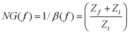
It is called the noise gain because it is the dominant part of the voltage gain experienced by the op-amp input voltage noise and is identical
to the signal voltage gain of the non-inverting amplifier configuration. The noise gain will vary with frequency since Zf and Zi are in general complex impedances.
The noise-gain function is often approximated by a segmended Bode plot which provides good insight into circuit operation based on the position of zeros and poles.
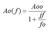
The essence of feedback loop stability is contained in the loop gain expression Ao(f)β(f)
or equivalently Ao(f)/NG(f) where Ao(f) is the op-amp open loop gain response, which for a simple single-pole response considered here is:
The frequency at which the magnitude of Ao(f)/NG(f) is unity (or equivalently the point at which the magnitude curves of Ao(f) and NG(f) intersect) must have a phase angle of less than 180 deg to ensure that
the feedback signal doesn't contribute to positive feedback and oscillation. Typically 45 degrees or more of phase margin (180 -Phase(Ao(f)/NG(f)) at the intersection point is adequate.
A very useful paremeter which neatly encapsulates the entire transimpedance circuit performance in terms of stability is the
Q or Quality Factor of the response.
Since the transimpedance circuit with the feedback network shown above is a second order low-pass filter, the circuit will display resonant behaviour in the transimpedance response,
identical to that of the classic LRC low pass filter (with output taken across the capacitor) driven with a voltage source. A high Q value corresponds to significant ringing in pulse response and significant
peaking in the frequency response. Generally a value of Q of 1 or lower, corresponding to a phase margin of greater than 50 degrees, is required to ensure stability in the transimpedance circuit.
A very common approach in stabilizing a transimpedance circuit is to adjust the feedback capacitance Cf so that the pole due to Rf and Cf is positioned at the intersection point
of the Bode-approximation noise-gain profile and the op-amp open-loop gain curve which simplifies the analysis somewhat and results in a value of Cf:
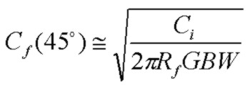
It is often stated that the phase margin associated with this value of Cf is 45 degrees which provides reasonable stability.
The phase margin is indeed 45 degrees at the pole frequency (assuming Cf << Ci). However the pole frequency is
not the true intersection point of the noise-gain and the open-loop gain curve and it is the phase margin at the true intersection point which determines the phase margin for stability.
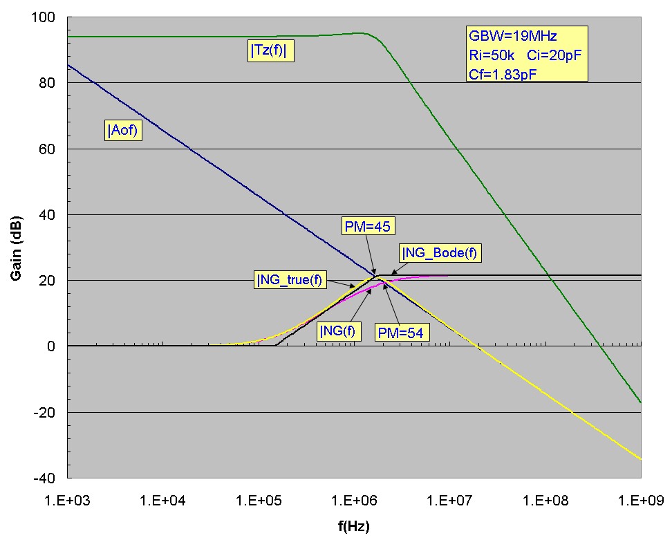
To demonstrate this, the plots below show a typical transimpedance amplifier circuit design with the value of Cf chosen using the equation above. The phase margin at Fp=1.74 MHz, the intersection point
of the Bode-approximated noise gain is shown and is 45 degrees. However it can clearly be seen that the noise-gain curve NG(f) in fact intersects the op-amp open-loop gain curve at
a higher frequency of 2.07 MHz and the phase margin at this intersection point is 54 degrees with a Q value of 0.96. Therefore, the commonly used value of Cf above underestimates the true phase margin
providing a conservative value for stability purposes. A slight peaking of 1dB in Tz(f) can be seen, associated with a Q value close to 1. Also it is not difficult to show that for this
Cf value, the
3db transimpedance bandwidth is not Fp
but is considerably higher (20%) and approximately equal to the real intersection frequency f3db ~ 2.07 MHz:
References